Pro-Ject Audio Systems Box Design Pro-Ject Tuner Box S2 Instructions For Use Manual Download Page 3

© Pro-Ject Audio Systems · Pro-Ject Tuner Box S2 · Revision 2018.11.27 


3


available as accessories. The remote power-on signal can be relayed to further units via the Trigger Output 
socket. When the 12V trigger signal is switched off, the unit will also switch off.  


Trigger cables may only be plugged into the sockets when the unit is disconnected from the power 
supply and from the mains. Failure to do so may result in damage of the unit. 

Mains power connection 

The  unit  is  supplied  with  a  power  supply  suitable  for  your  country's  mains  supply.  Check  the  label  before 
connecting to ensure compliance with the mains rating in your house. Connect the low voltage plug from the 

power supply to the Power 5V DC


socket before connecting the power supply to the mains. 
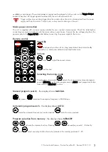
 

Remote control 


Stand-By


 short press turns the unit on, long press takes it back into standby. 

Powered on, a short press activates and deactivates mute 

Volume


 and 

 adjust the sound volume 

 no function


Selecting the tuning mode


Pressing (min. 3 seconds) 

 selects the tuning modes manual program 

search (MANUAL), automatic program search (AUTO) and program selection 
from memory (MEMORY) in turns.


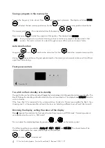
Manual program search 

- the display shows

 MANUAL 

 decreases, 

 increases the reception frequency in 50kHz steps. 

Automatic program search 

- the display shows

 AUTO 

 starts the automatic frequency scan downwards, 

 starts the scan upwards. 

Program selection from memory 

-


the display shows

 MEMORY 

 - 

 activate the memory function. Pressing 

 - 

 access the pre-sets 1 - 8 directly. 

 and 

 select -memory function has to be activated- the memory positions 9 - 99. 


Summary of Contents for Box Design Pro-Ject Tuner Box S2

Page 1: ...INSTRUCTIONS FOR USE Pro Ject Tuner Box S2 ...

Page 2: ...s whilst the tuner is disconnected from the power supply Take care to connect the left and right channels correctly The right channel is usually marked red the left channel black or white Connection to an amplifier Connect the output Out to any line livel input on the pre amplifier Antenna input Connects to any antenna cable with a co axial DIN plug US model F plug Mains power connection and metho...

Page 3: ...y to the Power 5V DC socket before connecting the power supply to the mains Remote control Stand By short press turns the unit on long press takes it back into standby Powered on a short press activates and deactivates mute Volume and adjust the sound volume no function Selecting the tuning mode Pressing min 3 seconds selects the tuning modes manual program search MANUAL automatic program search A...

Page 4: ...ufficient signal level while storing Front panel controls To switch on from standby or to standby The push button on the left hand side will toggle the tuner between its fully operational status and standby The blue LED above the stand by push button shows that the unit is switched on The display shows STANDBY when the unit is in standby If the Tuner Box S2 is connected to the remote switch on fac...

Page 5: ...re shown signal strength meter and B two loudspeaker symbols are shown F one loudspeaker symbol shows mono reception C the vertical bar is centred in the fine tuning display Automatic program search Press approx 3 seconds repeatedly until the display shows AUTO starts the automatic frequency scan upwards will start it downwards The maximum signal strength will be adjusted automatically for each pr...

Page 6: ... 1 x co axial DIN socket 75 ohms US model F socket Line level output 1 pair RCA phono sockets Trigger in and out 2 pole co axial 2 5mm co axial jack Output voltage 0 775Vrms Outboard power supply 5V 1A DC 110 240V 50 60Hz Power consumption 70mA DC 1W in standby Dimensions W x H x D D with sockets 103 x 37 x 112 121 mm Weight 315g without power supply Service Should you encounter a problem which yo...

Reviews: