background image

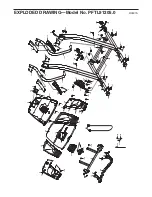
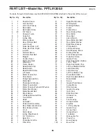
To locate the parts listed below, see the EXPLODED DRAWING attached in the center of this manual.

26

PART LIST—Model No. PFTL91205.0

R0507A

1

2

Foot Rail Cover

2

1

Left Foot Rail

3

1

Left Front Endcap

4

2

Belt Guide

5

4

Belt Guide Screw

6

40

3/4” Screw

7

1

Console Frame

8

4

Cage Nut

9

1

Incline Wire

10

1

Warning Decal

11

2

Rear Platform Bolt

12

1

Latch Cover

13

1

Pulse Bar Plate, Left

14

1

Pulse Bar Plate, Right

15

2

Isolator

16

2

Platform Screw

17

2

Platform Pivot Bolt

18

1

Magnet

19

2

Caution Decal

20

1

Motor Pivot Bolt

21

7

Wheel Nut

22

2

Frame Spacer

23

1

Reed Switch Clip

24

1

Reed Switch

25

1

Reed Switch Screw

26

1

Lift Frame

27

2

Motor Tension Nut

28

1

Drive Motor

29

1

Pulley/Flywheel/Fan

30

1

Motor Belt

31

1

Photo Switch Washer

32

2

Motor Tension Bolt

33

5

Motor Tension Washer/Lift Washer

34

1

Motor Star Washer

35

2

Motor Bracket Bolt

36

7

Small Screw

37

1

Lift/Upright Ground Wire

38

1

Transformer

39

1

Hood

40

1

Controller

41

1

Power Cord Assembly

42

2

Rear Roller Star Washer

43

8

Rear Endcap Screw

44

4

U-nut

45

1

Static Decal

46

1

Incline Stop Bracket

47

17

3/4” Tek Screw

48

1

Belly Pan

49

1

Photo Switch Wire

50

1

Filter Wire

51

1

Right Front Endcap

52

1

Walking Belt

53

1

Walking Platform

54

1

Frame

55

2

Platform Nut

56

2

Rear Endcap Plate

57

1

Rear Roller

58

2

Rear Foot

59

1

Allen Wrench

60

2

Rear Roller Adj. Bolt

61

2

Rear Roller Washer

62

1

Right Rear Endcap

63

1

Photo Switch

64

1

Left Rear Endcap

65

2

Small Endcap Screw

66

2

Endcap Washer

67

4

Front Endcap Screw

68

4

Pulse Bar Screw

69

2

Isolator Plate

70

1

Right Cup Holder, Bottom

71

4

1/4” x 1” Bolt

72

1

Right Cup Holder, Top

73

1

Left Cup Holder, Bottom

74

1

Latch Assembly

75

1

Latch Housing

76

1

Left Cup Holder, Top

77

1

Photo Switch Bolt

78

1

Right Handgrip Bottom

79

1

Book Holder

80

6

Screw

81

4

Isolator Plate Screw

82

1

Incline Motor

83

1

Wire Harness

84

2

Isolator Housing

85

1

Optic Disk

86

1

Right Foot Rail

87

1

Console Fan

88

1

Console

89

1

Fan Housing

90

2

Center Isolator

91

1

Key/Clip

92

4

1/4” Star Washer

93

2

Isolator Cap

94

1

Access Door

95

1

Console Back

96

1

Tie Holder

97

1

Releasable Tie

98

9

Plastic Tie

99

2

Base Endcap

100

4

Base Pad

Key No. Qty.

Description

Key No. Qty.

Description

Summary of Contents for PFTL91205.0

Page 1: ...91205 0 Serial No QUESTIONS As a manufacturer we are com mitted to providing complete customer satisfaction If you have questions or if parts are damaged or missing PLEASE CONTACT OUR CUSTOMER SERVICE...

Page 2: ...PERATION 10 HOW TO FOLD AND MOVE THE TREADMILL 19 TROUBLESHOOTING 21 EXERCISE GUIDELINES 23 PART LIST 26 ORDERING REPLACEMENT PARTS Back Cover LIMITED WARRANTY Back Cover Note An EXPLODED DRAWING is a...

Page 3: ...ations described on page 10 To purchase a surge suppressor see your local PROFORM dealer or call the toll free telephone number on the front cover of this manual and order part number 146148 or see yo...

Page 4: ...resentative only 24 The treadmill is intended for in home use only Do not use the treadmill in any commercial rental or institutional setting WARNING Before beginning this or any exercise program cons...

Page 5: ...ual To help us assist you note the product model number and serial number before contacting us The model number of the treadmill is PFTL91205 0 The serial number can be found on a decal attached to th...

Page 6: ...re cutters For help identifying assembly hardware see the drawings below Note The assembly hardware and other small parts are packaged in separate part bags If a part is not found in the part bags che...

Page 7: ...bove Note There is not a wire harness in the left Upright 109 2 109 109 83 122 122 Brace Left Handrail Right Handrail Hole 112 112 3 With the help of another person hold the console as sembly near the...

Page 8: ...the hole Hold the Latch Housing in place and tighten the two 3 4 Screws 6 Be careful not to overtighten the Screws Pull the knob to the right and carefully lower the Frame 54 to the floor Note After a...

Page 9: ...from the back of the Console Back 95 2 Connect the wire on the receiver A to the indicated wire extending from the Console Back 95 Next remove the paper from the adhesive pad on the back of the receiv...

Page 10: ...own grounding provides a path of least resistance for electric current to reduce the risk of elec tric shock This product is equipped with a cord having an equipment grounding conductor and a groundin...

Page 11: ...ly controls the speed and in cline of the treadmill as it guides you through an effec tive workout Two pulse programs are also offered Each program automatically adjusts the speed and incline of the t...

Page 12: ...Speed increase button is pressed the walking belt will begin to move at 1 mph As you exercise change the speed of the walking belt as desired by pressing the Speed in crease and decrease buttons Each...

Page 13: ...f you use the handgrip pulse sensor and the optional chest pulse sensor at the same time the console will not display your heart rate accu rately Before using the handgrip pulse sensor first remove th...

Page 14: ...l flash to alert you When the first segment ends all speed settings will move one column to the left The speed setting for the second segment will then be shown in the flashing Current Segment column...

Page 15: ...rogram ends make sure that the in cline of the treadmill is at the lowest setting Next remove the key from the console and put it in a secure place Note If the displays and various indicators on the c...

Page 16: ...Press the Start button or the Speed increase button to start the program A moment after the button is pressed the tread mill will automatically adjust to the first speed and incline settings of the p...

Page 17: ...the target heart rate setting If your pulse is not detected during the program the letters PLS will flash in the Calories Pulse display and the speed of the treadmill may auto matically decrease If t...

Page 18: ...Pace display will show the total number of hours the treadmill has been used IMPORTANT The Calories Pulse display should be blank If a d appears in the display the console is in the demo mode This mod...

Page 19: ...ully inserted into the hole in the left handgrip Note After a period of use the latch housing may need to be adjusted to align the pin with the hole in the left handgrip see assembly step 5 on page 8...

Page 20: ...ob to the right Pivot the frame down until the pin on the latch knob is below the handgrip Then slowly release the latch knob 2 Hold the frame firmly with both hands and lower the frame to the floor T...

Page 21: ...e circuit breaker wait for five minutes and then press the breaker back in PROBLEM The power turns off during use SOLUTION a Check the reset off circuit breaker see the drawing above If the circuit br...

Page 22: ...ug in the power cord insert the key and run the tread mill for a few minutes Repeat until the walking belt is properly tightened c If the walking belt still slows when walked on see the front cover of...

Page 23: ...mounts of oxygen for prolonged periods of time This increases the demand on the heart to pump blood to the muscles and on the lungs to oxygenate the blood For aerobic exercise adjust the speed or incl...

Page 24: ...les Stretch With one leg in front of the other reach forward and place your hands against a wall Keep your back leg straight and your back foot flat on the floor Bend your front leg lean forward and m...

Page 25: ...25 NOTES...
Page 26: ...43 8 Rear Endcap Screw 44 4 U nut 45 1 Static Decal 46 1 Incline Stop Bracket 47 17 3 4 Tek Screw 48 1 Belly Pan 49 1 Photo Switch Wire 50 1 Filter Wire 51 1 Right Front Endcap 52 1 Walking Belt 53 1...

Page 27: ...itch Nut 119 1 Front Roller Adj Bolt 120 1 Front Roller Pulley 121 2 Round Base Pad 122 4 5 16 x 1 Bolt 123 2 Handrail 124 1 Left Handgrip Top 125 1 Left Handgrip Bottom 126 1 Right Endcap Insert 127...

Page 28: ...6 6 47 41 40 6 48 6 21 21 120 67 55 55 65 67 6 119 66 117 115 15 4 5 75 74 47 47 80 65 66 64 60 61 43 58 15 5 4 6 93 90 81 69 84 47 81 69 47 93 90 104 84 6 33 33 43 43 12 80 32 56 126 113 56 127 129...

Page 29: ...6 73 6 6 6 6 70 6 6 6 130 114 19 19 8 8 47 100 47 100 47 100 105 47 100 6 6 6 6 6 6 94 95 111 21 21 82 85 77 31 63 118 103 46 78 123 123 116 124 6 112 112 105 122 122 44 125 6 44 47 121 121 47 21 108...

Page 30: ...e customer will be responsible for a minimal trip charge This warranty does not extend to any product or damage to a product caused by or attributable to freight damage abuse misuse im proper or abnor...

Reviews: