background image

24

These guidelines will help you to plan your exercise 

program. For detailed exercise information, obtain a 

reputable book or consult your physician. Remember, 

proper nutrition and adequate rest are essential for 

successful results. 

EXERCISE INTENSITY

Whether your goal is to burn fat or to strengthen your 

cardiovascular system, exercising at the proper inten-

sity is the key to achieving results. You can use your 

heart rate as a guide to find the proper intensity level. 

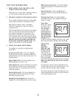
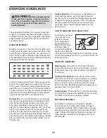
The chart below shows recommended heart rates for 

fat burning and aerobic exercise.

To find the proper intensity level, find your age at the 

bottom of the chart (ages are rounded off to the near-

est ten years). The three numbers listed above your 

age define your “training zone.” The lowest number is 

the heart rate for fat burning, the middle number is the 

heart rate for maximum fat burning, and the highest 

number is the heart rate for aerobic exercise.

Burning Fat—To burn fat effectively, you must exer-

cise at a low intensity level for a sustained period of 

time. During the first few minutes of exercise, your 

body uses carbohydrate calories for energy. Only 

after the first few minutes of exercise does your body 

begin to use stored fat calories for energy. If your 

goal is to burn fat, adjust the intensity of your exer-

cise until your heart rate is near the lowest number in 

your training zone. For maximum fat burning, exercise 

with your heart rate near the middle number in your 

training zone.

Aerobic Exercise—If your goal is to strengthen your 

cardiovascular system, you must perform aerobic 

exercise, which is activity that requires large amounts 

of oxygen for prolonged periods of time. For aerobic 

exercise, adjust the intensity of your exercise until 

your heart rate is near the highest number in your 

training zone. 

HOW TO MEASURE YOUR HEART RATE

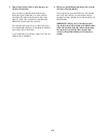
To measure your heart 

rate, exercise for at 

least four minutes. 

Then, stop exercis-

ing and place two 

fingers on your wrist 

as shown. Take a 

six-second heartbeat 

count, and multiply the 

result by 10 to find your heart rate. For example, if your 

six-second heartbeat count is 14, your heart rate is 140 

beats per minute.

WORKOUT GUIDELINES

Warming Up—Start with 5 to 10 minutes of stretch-

ing and light exercise. A warm-up increases your body 

temperature, heart rate, and circulation in preparation 

for exercise. 

Training Zone Exercise—Exercise for 20 to 30 min-

utes with your heart rate in your training zone. (During 

the first few weeks of your exercise program, do not 

keep your heart rate in your training zone for longer 

than 20 minutes.) Breathe regularly and deeply as you 

exercise; never hold your breath. 

Cooling Down—Finish with 5 to 10 minutes of stretch-

ing. Stretching increases the flexibility of your muscles 

and helps to prevent post-exercise problems.

EXERCISE FREQUENCY

To maintain or improve your condition, complete 

three workouts each week, with at least one day of 

rest between workouts. After a few months of regular 

exercise, you may complete up to five workouts each 

week, if desired. Remember, the key to success is to 

make exercise a regular and enjoyable part of your 

everyday life.

    WARNING:

 Before beginning this 

or any exercise program, consult your physi-

cian. This is especially important for persons 

over age 35 or persons with pre-existing 

health problems.

EXERCISE GUIDELINES

Summary of Contents for LE TOUR DE FRANCE CLC

Page 1: ... this equipment Keep this manual for future reference Serial Number Decal USER S MANUAL proform com To register your product and activate your warranty today go to my proform com For service at any time go to support proform com Or call 1 866 362 4490 Mon Fri 6 a m 6 p m MT Sat 8 a m 12 p m MT Please do not contact the store ACTIVATE YOUR WARRANTY CUSTOMER CARE ...

Page 2: ...ation s of the warning decal s If a decal is missing or illegible see the front cover of this manual and request a free replacement decal Apply the decal in the location shown Note The decal s may not be shown at actual size PROFORM and IFIT are registered trademarks of ICON Health Fitness Inc LE TOUR DE FRANCE is a regis tered trademark of Société du Tour de France The Bluetooth word mark and log...

Page 3: ...re and dust Do not put the exercise bike in a garage or covered patio or near water 7 Place the exercise bike on a level surface with a mat beneath it to protect the floor or carpet Make sure that there is at least 2 ft 0 6 m of clearance around the exercise bike 8 Inspect and properly tighten all parts each time the exercise bike is used Replace any worn parts immediately 9 Keep children under ag...

Page 4: ...4 STANDARD SERVICE PLANS ...

Page 5: ...estions after reading this manual please see the front cover of this manual To help us assist you note the product model number and serial number before contacting us The model number and the location of the serial number decal are shown on the front cover of this manual Before reading further please familiarize yourself with the parts that are labeled in the drawing below Brake Knob Saddle Hand W...

Page 6: ...he PART LIST near the end of this manual The number following the key number is the quantity needed for assembly Note If a part is not in the hardware kit check to see if it has been preassembled Extra parts may be included M6 x 15mm Screw 71 4 M10 x 25mm Screw 69 4 M4 x 25mm Screw 6 1 M6 x 15mm Screw 71 4 M10 x 25mm Screw 69 4 M4 x 25mm Screw 6 1 M4 x 20mm Screw 81 1 M4 Nut 26 1 ...

Page 7: ...he included tool s assembly requires the following tool s one Phillips screwdriver one adjustable wrench one rubber mallet one pair of scissors Assembly may be easier if you have a set of wrenches To avoid damaging parts do not use power tools ASSEMBLY 1 Go to my proform com on your computer and register your product documents your ownership activates your warranty ensures priority customer suppor...

Page 8: ...f the Frame 1 remove and discard the shipping tubes and the hardware attaching them Orient the Front Stabilizer 2 as shown and attach it to the Frame 1 with two M10 x 25mm Screws 69 2 69 2 1 69 3 3 3 Attach the Rear Stabilizer 3 to the Frame 1 with two M10 x 25mm Screws 69 1 ...

Page 9: ...into an adjustment hole in the Saddle Post and then tighten the Adjustment Handle four turns Make sure that the Adjustment Handle is firmly engaged in an adjustment hole Then pull the Adjustment Handle 14 outward turn it so that it points downward as shown and then release it 10 11 71 12 71 5 Orient the Left and Right Weight Rests 11 12 as shown Attach each Weight Rest 11 12 to the Saddle Carriage...

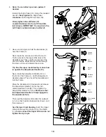
Page 10: ...he upper inset drawing to learn how to operate the Adjustment Handle 14 Next locate the Adjustment Handle 14 on the front of the Frame 1 Pull the Adjustment Handle outward Then insert the Handlebar 4 into the Frame Move the Handlebar 4 downward and release the Adjustment Handle 14 into the indi cated adjustment hole B Then tighten the Adjustment Handle four turns Make sure that the Adjustment Hand...

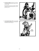
Page 11: ...Lower Wire 82 Next tighten the zip tie C around the indicated mark D on the Upper Wire 56 Then cut off the excess zip tie 8 56 82 C D 56 82 9 9 Tip Avoid pinching the wires Press the Motor Cover 38 onto the Frame 1 and then attach it with an M4 x 20mm Screw 81 81 38 1 Avoid pinching the wires C ...

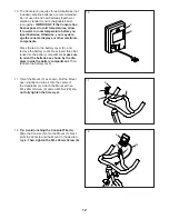
Page 12: ... battery cover E and remove the battery cover Next insert three bat teries into the battery compartment make sure to orient the batteries as shown by the dia gram inside the battery compartment Then reattach the battery cover E 5 11 Orient the Mount F as shown Pull the Mount open slightly and slide it onto the center of the Handlebar 4 Attach the Mount with an M4 x 25mm Screw 6 and an M4 Nut 26 do...

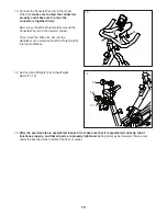
Page 13: ...ke to protect the floor or carpet 14 Set the Hand Weights 59 in the Weight Rests 11 12 59 59 11 12 13 Connect the Console Wire G to the Upper Wire 56 make sure to align the connectors properly and make sure to press the connectors together firmly Next press the Wire Protector 85 around the Console Wire G in the location shown Then insert the Wires G 56 into the Handlebar 4 and press the Wire Prote...

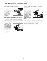
Page 14: ...a few turns and then tilt the saddle upward or downward or slide the saddle forward or backward to the desired position Then retighten the nuts HOW TO ADJUST THE HORIZONTAL POSITION OF THE SADDLE To adjust the position of the saddle first loosen the carriage handle C and pull it outward Then move the saddle forward or backward release the carriage handle and then firmly tighten the carriage handle...

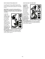
Page 15: ... an adjust ment hole in the saddle post and firmly tighten the adjustment han dle four turns Make sure that the adjustment handle is engaged in an adjustment hole Then pull the adjustment handle outward turn it so that it points downward as shown and then release it HOW TO ADJUST THE HANDLEBAR To adjust the height of the handlebar first loosen the adjust ment handle E four turns and pull it outwar...

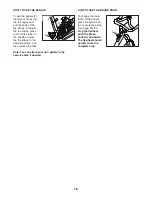
Page 16: ...uckles adjust the toe straps to the desired position and then release the tabs Note You can attach your own pedals to the exercise bike if desired HOW TO USE THE BRAKE KNOB To change the resis tance of the pedals press the buttons on the console see step 2 on page 18 To stop the flywheel push the brake knob G downward The flywheel should quickly come to a complete stop F F G ...

Page 17: ...patible heart rate monitor See page 21 for information about pur chasing an optional chest heart rate monitor You can also connect your tablet to the console and use the iFit Smart Cardio Equipment app to record and track your workout information To use the manual mode see page 18 To connect your tablet to the console see page 20 To connect your heart rate monitor to the console see page 20 Note I...

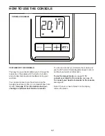
Page 18: ...s your heart rate in beats per minute when you are using the heart rate monitor or an optional chest heart rate monitor see step 4 Calories flame icon This mode displays the approximate number of calories that you have burned during your workout Resistance hand weight icon This mode displays the current resistance level of the pedals RPM circular arrow icon This mode displays your pedaling speed i...

Page 19: ...etected your heart rate will be shown If your heart rate is not shown make sure that the pulse mode is displayed 5 When you are finished exercising the console will turn off automatically The console has an auto off feature If the pedals are not moved and the console buttons are not pressed for a few minutes the console will turn off automatically IMPORTANT When you are finished exercis ing make s...

Page 20: ... When the your tablet is connected the Bluetooth icon will appear in the display 4 Record and track your workout information Follow the instructions in the iFit Smart Cardio Equipment app to record and track your workout information 5 Disconnect your tablet from the console if desired To disconnect your tablet from the console first select the disconnect option in the iFit Smart Cardio Equipment a...

Page 21: ... uses and can radiate radio frequency energy and if not installed and used in accordance with the instructions may cause harmful interference to radio communications However there is no guarantee that interference will not occur in a particular installation If this equipment does cause harmful interference to radio or television reception which can be determined by turning the equipment off and on...

Page 22: ...ly step 13 on page 13 First pull out the wire protector and pull out the wires Then disconnect the console wire from the upper wire and then recon nect the wires make sure to align the connectors properly and make sure to press the connectors together firmly Then press the wire protector into the handlebar HOW TO ADJUST THE REED SWITCH If the console does not display correct feedback the reed swit...

Page 23: ... to the highest level the drive belt may need to be adjusted To adjust the drive belt locate the Idler Cover 36 Remove the M4 x 12mm Blunt Screw 80 and the Idler Cover Then tighten the M10 x 60mm Screw 65 until the Drive Belt not shown is tight When the Drive Belt not shown is tight reattach the Idler Cover 36 65 80 36 ...

Page 24: ...orm aerobic exercise which is activity that requires large amounts of oxygen for prolonged periods of time For aerobic exercise adjust the intensity of your exercise until your heart rate is near the highest number in your training zone HOW TO MEASURE YOUR HEART RATE To measure your heart rate exercise for at least four minutes Then stop exercis ing and place two fingers on your wrist as shown Tak...

Page 25: ...5 1 Pulley 46 1 Drive Belt 47 1 Flywheel 48 1 Flywheel Axle 49 2 Flywheel Bearing 50 1 Flywheel Spacer 51 2 Wheel 52 2 Foot 53 2 Leveling Foot 54 4 Cap 55 1 Saddle Post Cap 56 1 Upper Wire 57 1 Reed Switch Wire 58 1 Clamp 59 2 Hand Weight 60 1 Flywheel Washer 61 4 Clip Nut 62 2 Magnet 63 4 M8 x 20mm Flat Head Screw 64 6 M8 Locknut 65 1 M10 x 60mm Screw 66 1 Crank Screw 67 1 Bracket Spacer 68 1 M10...

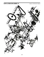
Page 26: ...7 20 21 23 28 30 30 32 25 22 24 27 29 31 84 34 36 38 39 33 35 37 43 43 46 48 50 52 45 42 42 44 44 47 49 49 51 58 57 60 61 61 61 63 66 68 65 62 62 64 64 67 69 69 72 74 76 78 80 80 80 80 80 80 80 81 75 83 75 83 80 73 77 81 81 81 61 80 81 70 81 80 80 81 79 81 81 81 53 54 54 15 ...

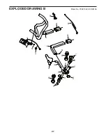
Page 27: ...27 EXPLODED DRAWING B Model No PFEX73920 0 R0919A 8 10 12 5 4 7 9 11 13 40 59 59 55 71 71 79 81 82 41 56 6 26 85 ...

Page 28: ...play model 2 if the product is purchased or transported outside the USA 3 if all instructions and warnings in this manual are not followed 4 if the product is abused or improperly or abnormally used or 5 if the product is used for commercial or rental purposes No other warranty beyond that specifically set forth above is authorized by ICON ICON is not responsible or liable for the following damage...

Reviews: