background image

7

4.

Tip: Be careful not to pinch the Wire

Harness (100).

Orient the Water Bottle Holder (5) as shown

and slide it onto the Upright (2). Attach the

Water Bottle Holder with two M4 x 32mm

Screws (95).

Slide the Console Cover (96) onto the Upright

(2) and move it downward to the Water Bottle

Holder (5). Then, insert the Console Bracket (3)

into the top of the Upright. Attach the Console

Bracket with four M4 x 16mm Screws (84).

4

3.

Tip: Be careful not to pinch the Wire

Harness (100). Start all screws before tight-

ening any of them.

Have another person hold the Upright (2) near

the Frame (1). Locate the wire tie in the Upright.

Tie the lower end of the wire tie to the Wire

Harness (100). Next, pull the upper end of the

wire tie upward out of the top of the Upright.

Then, untie and discard the wire tie.

Tip: To

prevent the Wire Harness from falling inside

the Upright (2), secure the Wire Harness

with a rubber band.

Attach the Upright (2) to the Frame (1) with four

M10 x 20mm Patch Screws (79), and four M10

Split Washers (78).

Tip: Tighten the two

Button Screws on the front of the elliptical

exerciser before tightening the other two

Button Screws.

3

Avoid pinching the

Wire Harness (100)

2

1

100

78

78

78

79

79

79

84

84

95

100

96

3

5

Wire Tie

2

Summary of Contents for 380 F Elliptical

Page 1: ...ʼS MANUAL QUESTIONS As a manufacturer we are commit ted to providing complete customer satisfaction If you have questions or if parts are damaged or missing DO NOT CONTACT THE STORE please contact Customer Care IMPORTANT You must note the product model number and serial number see the drawing above before contacting us CALL TOLL FREE 1 888 533 1333 Mon Fri 6 a m 6 p m MT Sat 8 a m 4 p m MT ON THE ...

Page 2: ...XPLODED DRAWING 22 ORDERING REPLACEMENT PARTS Back Cover LIMITED WARRANTY Back Cover 2 PROFORM is a registered trademark of ICON IP Inc WARNING DECAL PLACEMENT This drawing shows the location s of the warning decal s If a decal is missing or illegible see the front cover of this manual and request a free replacement decal Apply the decal in the location shown Note The decal s may not be shown at a...

Page 3: ...0 lbs 113 kg 8 Wear appropriate exercise clothes when exercising do not wear loose clothes that could become caught on your elliptical exer ciser Always wear athletic shoes for foot protection 9 Hold the handgrip pulse sensor or the upper body arms when mounting dismounting or using your elliptical exerciser 10 Keep your back straight while using your elliptical exerciser do not arch your back 11 ...

Page 4: ...al carefully before you use the elliptical exerciser If you have ques tions after reading this manual please see the front cover of this manual To help us assist you note the product model number and serial number before con tacting us The model number and the location of the serial number decal are shown on the front cover of this manual To avoid a registration fee for any service needed under wa...

Page 5: ...erciser use the drawings below to identify small parts The number in parenthe ses below each drawing is the key number of the part from the PART LIST near the end of this manual The number following the parentheses is the quantity needed for assembly Note Some small parts may have been preassembled If a part is not in the hardware kit check to see if it has been preassembled M4 x 16mm Screw 84 12 ...

Page 6: ...h an L sticker Orient the Left and Right Frame Covers 48 49 with the rounded sides in the indicated locations While another person lifts the rear of the Frame 1 attach each Frame Cover 48 49 to the Frame with two M4 x 16mm Screws 84 48 Rounded Side 1 Rounded Side 1 To make assembly easier read the information on page 5 before you begin assembling the elliptical exerciser 84 63 50 1 63 50 84 49 ...

Page 7: ...of them Have another person hold the Upright 2 near the Frame 1 Locate the wire tie in the Upright Tie the lower end of the wire tie to the Wire Harness 100 Next pull the upper end of the wire tie upward out of the top of the Upright Then untie and discard the wire tie Tip To prevent the Wire Harness from falling inside the Upright 2 secure the Wire Harness with a rubber band Attach the Upright 2 ...

Page 8: ...re where you purchased this product or call the telephone number on the cover of this manual To avoid damaging the console use only a manufacturer supplied AC adapter Plug one end of the AC adapter into the jack on the console plug the other end into an outlet installed in accordance with all local codes and ordinances 5 6 While a second person holds the Console 4 near the Upright 2 connect the co...

Page 9: ... L sticker Orient the Left Upper Body Arm and the left Upper Body Leg 6 as shown make sure that the hexagonal holes in the Left Upper Body Arm are in the indicated location Slide the Left Upper Body Arm 8 onto the left Upper Body Leg 6 Attach the Left Upper Body Arm with two M6 x 38mm Button Bolts 76 and two M6 Locknuts 77 make sure that the Locknuts are inside the hexagonal holes Repeat this step...

Page 10: ...ease 12 Make sure that all parts of the elliptical exerciser are properly tightened Note Some hardware may be left over after assembly is completed To protect the floor or carpet from damage place a mat under the elliptical exerciser 11 Apply a small amount of grease to a Pedal Arm Axle 21 While another person holds the right Pedal Arm 14 inside the bracket on the right Upper Body Leg 6 insert the...

Page 11: ...cal exerciser hold the upper body arms and step onto the pedal that is in the lowest position Next step onto the other pedal Push the pedals until they begin to move with a continuous motion Note The crank arms can turn in either direction It is recommended that you turn the crank arms in the direction shown by the arrow below however for variety you can turn the crank arms in the opposite directi...

Page 12: ... adjustment bracket until the adjustment knob is aligned with one of the holes in the crank arm and gently release the knob Then pivot the adjustment bracket back and forth slightly to make sure that the adjustment pin is engaged in one of the holes in the crank arm Adjust the other side of the elliptical exerciser in the same way Adjustment Knob Crank Arm Holes Adjustment Bracket Adjustment Pin ...

Page 13: ...nsor The console features two target tone workouts designed to work specific areas of the body The con sole guides you through each workout with a variety of exercise instructions while automatically changing the resistance of the pedals The console also offers four preset workouts Each preset workout automatically changes the resistance of the pedals and prompts you to increase or decrease your p...

Page 14: ...apsed time The lower left display This display can show the elapsed time and the approximate num ber of calories you have burned Note During a work out the display will show the time remaining in the workout The upper middle dis play This display will show the resistance level of the pedals for a few seconds each time the resistance level changes This display will also show your heart rate when yo...

Page 15: ...ure that your hands are positioned as described Be careful not to move your hands excessively or to squeeze the metal contacts tightly For optimal performance clean the metal contacts using a soft cloth never use alcohol abrasives or chemicals to clean the contacts 6 Turn on the fan if desired The fan has high and low speed settings Press the Fan button repeatedly to select a fan speed or to turn ...

Page 16: ...xample the console may instruct you to PEDAL BACKWARD USE UPPER BODY or FOCUS LOWER BODY during certain segments of the workout You will also be prompted to keep your pedaling pace near the target pace setting for the current segment When the TOO SLOW indicator is lit increase your pace When TOO FAST indicator is lit decrease your pace When the center indicator is lit maintain your current pace IM...

Page 17: ... keep your pedaling pace near the target pace setting for the current segment When the TOO SLOW indicator is lit increase your pace When TOO FAST indicator is lit decrease your pace When the center indicator is lit maintain your current pace IMPORTANT The target pace settings are intended only to provide motivation Make sure to pedal at a pace that is comfortable for you If the resistance level fo...

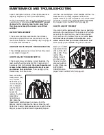
Page 18: ... the Magnet 41 is aligned with the Reed Switch Loosen but do not remove the indi cated M4 x 16mm Screw 84 Slide the Reed Switch slightly closer to or away from the Magnet and then retighten the Screw Rock the Left Pedal Disc forward and backward just enough that the Magnet passes the Reed Switch repeatedly Repeat until the console displays correct feedback When the Reed Switch is correctly adjuste...

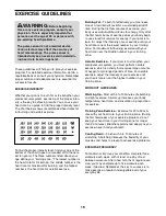
Page 19: ...our goal is to strengthen your cardiovascular system you must perform aerobic exercise which is activity that requires large amounts of oxygen for prolonged periods of time For aerobic exercise adjust the intensity of your exercise until your heart rate is near the highest number in your training zone WORKOUT GUIDELINES Warming Up Start with 5 to 10 minutes of stretching and light exercise A warm ...

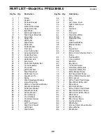
Page 20: ... Bearing 39 1 Crank Spacer 40 1 Crank Arm Spacer 41 2 Magnet 42 1 Left Front Shield 43 1 Right Front Shield 44 1 Left Shield 45 1 Right Shield 46 1 Belt 47 2 Foot 48 1 Left Frame Cover 49 1 Right Frame Cover 50 2 Wheel 51 1 Flywheel 52 1 Idler 53 1 C magnet 54 1 Resistance Motor 55 1 Motor Bracket 56 1 Resistance Arm 57 1 Clamp 58 1 Reed Switch Wire 59 1 Magnet Spacer 60 1 Key 61 1 Square Nut 62 1...

Page 21: ...6 Washer 91 4 M4 x 48mm Screw 92 12 M4 x 25mm Screw 93 4 M4 x 35mm Screw 94 4 M4 x 16mm Flat Head Screw 95 2 M4 x 32mm Screw 96 1 Console Cover 97 2 M8 x 18mm Button Screw 98 7 M5 x 12mm Screw 99 1 M3 x 12mm Screw 100 1 Wire Harness 101 1 Extended Reed Switch Wire 102 1 Left Adjustment Bracket Userʼs Manual Assembly Tool Grease Packet Key No Qty Description Key No Qty Description ...

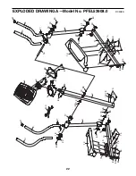
Page 22: ... R0908A 2 3 4 5 6 6 8 9 10 10 11 11 12 13 14 14 15 15 16 17 17 18 18 19 19 20 20 21 21 22 22 22 22 23 23 23 23 73 73 82 82 75 75 76 77 76 77 78 78 79 79 80 80 80 80 80 80 94 84 84 84 84 88 88 89 89 89 95 96 84 79 78 84 84 100 78 78 78 78 86 86 ...

Page 23: ...37 87 37 38 38 39 40 41 41 42 43 44 45 46 47 47 48 49 50 50 51 52 53 54 55 56 57 58 59 85 85 90 61 62 63 63 64 65 66 67 68 69 70 71 72 97 81 97 74 74 90 93 92 92 93 92 84 84 98 98 98 93 92 91 92 92 91 84 60 83 83 83 99 7 84 91 92 93 91 82 101 EXPLODED DRAWING B Model No PFEL53908 0 R0908A ...

Page 24: ...responsible for a minimal handling charge For in home service the customer will be responsible for a minimal trip charge This warranty does not extend to any damage to a product caused by or attributable to freight damage abuse misuse improper or abnormal usage or repairs not provided by an ICON authorized service center products used for commercial or rental purposes or products used as store dis...

Reviews: