VISTEK V1667, V1667/SY & V1667/SY-VHS
12-bit pal/ntsc to sdi adaptive
comb filter decoder
HU-V1667&SY&SY-VHS
7
3.
FRONT PANEL LAYOUT
See Section
8.3 VHS Input Option
for a description of the VHS decoding option.
REM
+V
NTSC
443
Local
Rem
V1667
12 Bit Decoder
CVBS to SDI
Select
CAL
+
-
I
M
N
Std.
VGain
CGain
Phase
Setup
PAL
Remote Control Access and Power indicators
Standard and Page indicators
Parameter indicators:
SELECT Button
UP Button
CAL / NORMALISED LED
DOWN Button
REMOTE / LOCAL control selection
AUTO
UNCAL LED (+)
UNCAL LED (-)
A
B
C
D
E
Sig
Tim
Anc
Named for Top Page
A - E for other Pages
VHS
VHS input selection:-
Only available on V1667/SY-VHS product
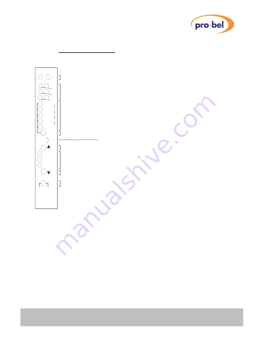
The V1667 has a versatile front panel, shown above. Commonly used controls are directly available, whilst
the less used ones are protected from inadvertent use. The panel uses the concept of
Pages
and
Parameters
. Within each
Page
there are a possible 5 adjustable
Parameters
.
There is provision for 5 pages in total, although only 3 are currently used. These are:
Top page (normal operation)
This is the normal operating page. The unit will always enter this page at
power up.
See 4. FRONT PANEL DESCRIPTION (NORMAL OPERATION)
Timing Page
This page is used to adjust the Frame Synchroniser timing parameters
and input failure modes, and is accessible only when a Frame
Synchroniser module is fitted to the card.
See 5. TIMING PAGE (FRAME SYNCHRONISER)
Engineering Page
This page is used to make changes to the decoder processing that it is
considered the user will only need to access infrequently (VITS
pass/blank, etc..)
See 6. ENGINEERING PAGE


