background image

11

Components on the Right Side of the Printer

Components on the Right Side of the Printer

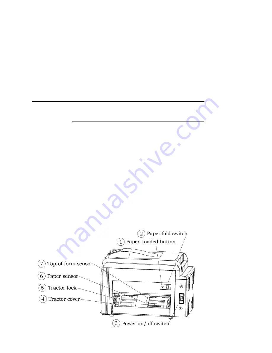
Figure 4 shows the controls on the right (paper-input) side of the 
printer.

IMPORTANT

Note the location of the power on/off switch. In the event of an 
emergency, use this switch to turn the printer off.

After reloading paper, pressing the Paper Loaded button restarts 
printing.

The paper fold switch tells an optional auto-fed power paper 
stacker how to stack the output paper. This switch is used only with 
auto-fed power paper stackers.

The paper sensor tells the printer whether paper is loaded and 
signals the printer when the paper runs out. When you reload 
paper, the top-of-form sensor tells the printer where the top of the 
first page is. The printer uses this information to start the printed 
image at the correct position on the paper.

Figure 4. Paper Input Side of Printer

Summary of Contents for L7032

Page 1: ...L7032 Laser Printer Quick Setup Guide ...

Page 2: ......

Page 3: ...e in English French German Italian Russian and Spanish The User s Manuals for optional paper stackers Printer drivers The CD ROM is in a plastic pocket in the back cover Save this Setup Guide If you move or re ship the printer in the future you can reverse the instructions in this guide to repack the printer NOTICE ...

Page 4: ...representations or warranties of any kind regarding this material including but not limited to implied warranties of merchantability and fitness for a particular purpose Printronix shall not be held responsible for errors contained herein or any omissions from this material or for any damages whether direct or indirect incidental or consequential in connection with the furnishing distribution perf...

Page 5: ...13 Components Inside the Printer 14 Unpack the Cardboard Buffer 16 Remove the Orange Tape Strips 16 Install the Fuser Cleaning Roller Ozone Filter Power Cord 20 Install the Developer Mix 23 Initialize the Developer Unit 31 Install and Remove the Seal From the Toner Cartridge 32 Load Paper 37 Make A Test Print 40 Contact Information 41 Printronix Customer Support Center 41 Printronix Supplies Depar...

Page 6: ...Table of Contents 6 ...

Page 7: ...re 1 shows the minimum clearances you need to install operate and maintain the printer You need a space at least 80 inches 2032 mm wide more if you have the optional power paper stacker and 55 inches 1397 mm deep 1 You need at least 28 inches 711 2 mm at the front of the printer to open the front access door and replace consumables 2 You need at least 28 inches 711 2 mm on the paper input side of ...

Page 8: ...he Printer 8 NOTE Direct sunlight will not damage the printer Direct sunlight may change the color of the printer s plastic surfaces as it would change the color of any plastic surface Figure 1 Correct Printer Positioning ...

Page 9: ... s components as you set up and operate the printer Front of the Printer Figure 2 shows the components on the front of the printer The use of the words LEFT and RIGHT assumes you are viewing the front of the printer unless otherwise noted For example the paper enters on the RIGHT side of the printer and exits on the LEFT side of the printer Figure 2 The Front of the Printer ...

Page 10: ...ow Feed paper forward Shift Up Arrow Exit Shift Down Arrow Enter Shift Right Arrow Feed paper backward Figure 3 also shows the three status lights on the operator panel Ready Data and On Line The operator panel displays messages menus and printing parameters on a liquid crystal display LCD Figure 3 Operator Panel For more information about the operator panel see Chapter 2 Printer Operation in the ...

Page 11: ...Loaded button restarts printing The paper fold switch tells an optional auto fed power paper stacker how to stack the output paper This switch is used only with auto fed power paper stackers The paper sensor tells the printer whether paper is loaded and signals the printer when the paper runs out When you reload paper the top of form sensor tells the printer where the top of the first page is The ...

Page 12: ...Location of Printer Components 12 Components on the Left Side of the Printer Figure 5 shows the component on the left paper exit side of the printer Figure 5 Paper Exit Side of Printer ...

Page 13: ...or by placing your fingers in the door grip on the left front side of the printer and pulling out on the door Figure 7 shows the components attached to the printer s front access door the main charger unit sensor and the seal for waste toner bottle The seal provides a closed connection between the OPC module s cleaner and the waste toner bottle The main charger unit sensor prevents the front acces...

Page 14: ...nter Components 14 Figure 7 Inside of Printer s Front Access Door Components Inside the Printer Figure 8 shows the consumables inside the printer Figure 8 Consumables Inside Printer Consumables Re ordering Information ...

Page 15: ...15 Components Inside the Printer Figure 9 shows the locking components and wire cleaning brush which are visible when the printer s door is open Figure 9 Latching Components and Wire Cleaning Brush ...

Page 16: ...rinter Accessories Included in Shipping Box Remove the Orange Tape Strips 1 Remove the two orange tape strips that hold the printer s front access door to the fuser drawer 2 Remove the orange tape strip that holds the fuser drawer to the back cover 3 Open the printer s front access door and remove the two orange tape strips that hold the following components to the printer s front frame Exit rolle...

Page 17: ... place Open the latch bar by swinging it to the left 5 Grasp the OPC module s black handle and pull it forward See Figure 11 CAUTION Avoid exposing the surface of the OPC drum to ambient light for more than five minutes Exposing the OPC drum to light for extended periods will degrade the photoconductors Figure 11 Pulling the OPC Module Forward ...

Page 18: ...Removing the OPC Module 7 Set the OPC module on a clean flat surface Cover the OPC module with an opaque covering so that no light can reach the OPC drum Use any convenient opaque covering such as a cardboard box a large sheet of paper or a large cloth 8 Remove the two orange tape strips holding the waste toner bottle and transfer charger unit in place One piece of tape holds both the waste toner ...

Page 19: ...o the transfer station You will remove the final three pieces of orange shipping tape when you install the fuser cleaning roller and the developer mix One piece of tape holds the top of the fuser unit closed Two pieces of tape hold the metal door on the top of the developer unit closed ...

Page 20: ...umables in the accessories box the fuser cleaning roller ozone filter and power cord 1 Turn the fuser latch counterclockwise slightly until it releases the fuser drawer on the left side of the printer See Figure 13 Figure 13 Releasing the Fuser Drawer 2 Make sure the fuser drawer is all the way out of the printer The drawer should be latched open See Figure 14 ...

Page 21: ... Released 3 Remove the orange shipping tape strip holding the top of the fuser unit closed Open the top of the fuser unit by pushing the black tab toward the inside of the printer See Figure 15 Figure 15 Opening the Fuser Unit ...

Page 22: ...ch Push the fuser drawer into the printer until it latches 7 Install the new ozone filter shown in Figure 10 on page 16 in the ozone filter opening on the back of the printer Push it all the way into the opening See Figure 16 Figure 16 Installing the Ozone Filter and Connecting the Power Cord 8 Make sure the printer s voltage matches the voltage of your electrical outlet by checking the certificat...

Page 23: ...se care when working with it 1 Remove the developer unit from the printer carefully Grasp its green handle with your left hand and pull it forward slowly See Figure 17 CAUTION The developer unit is heavy Do not pull it all the way out of the printer with one hand Figure 17 Pulling the Developer Unit Forward ...

Page 24: ...hand to support it See Figure 18 CAUTION Do not grasp the developer unit s handle with your right hand and reach under the unit with your left hand The lower left side of the developer unit has a roller which you should not touch Figure 18 Supporting the Developer Unit 3 Set the developer unit on a clean flat surface ...

Page 25: ...rips holding the metal door on the top of the developer unit closed Open the metal door by pressing on the small metal tabs at each end and pulling the tabs toward you See Figure 19 Figure 19 Opening the Metal Door on the Developer Unit ...

Page 26: ...Install the Developer Mix 26 5 Cut off one corner of the developer mix bag to make a spout See Figure 20 Figure 20 Bag of Developer Mix with Corner Cut Off ...

Page 27: ...See Figure 21 Figure 21 Evenly Distributing the Developer Mix in the Trough of the Developer Unit 7 Close the metal door that covers the developer unit s trough 8 Pick up the developer unit by grasping its handle with your left hand and placing your right hand underneath it 9 Gently shake the developer unit from side to side to distribute the developer mix evenly across the developer unit s trough...

Page 28: ...ch See Figure 22 To avoid catching the developer unit on the upper part of the printer you may need to angle the developer unit down slightly as you move it into the printer Figure 22 Putting the Developer Unit in the Printer 11 After the new developer unit is on the black plastic guide and has cleared the upper part of the printer push it all the way into the printer The developer unit will not l...

Page 29: ...light for an extended period will degrade the photoconductors CAUTION Do not touch the OPC drum Touching the OPC drum can contaminate the surface and degrade the print quality 13 Grasp the OPC module by its plastic handle and put the module back in the printer See Figure 23 Figure 23 Installing the OPC Module 14 Close the latch bar by swinging it up against the printer ...

Page 30: ...Install the Developer Mix 30 15 Rotate the green latch counterclockwise to lock the latch bar and developer unit in place See Figure 24 Figure 24 Closing the Latch on the Latch Bar ...

Page 31: ...RATIONS 4 Press left arrow or right arrow until you see MAIN MENU CONSUMABLES on the display 5 Press down arrow to select the CONSUMABLES menu 6 Press left arrow or right arrow until you see CONSUMABLES INIT DEVELOPER on the display 7 Press SHIFT to select 8 Use or to select No or Yes to continue then use SHIFT to begin the initialization Initializing the developer unit takes about 190 seconds a l...

Page 32: ...ot be able to rotate it any farther Figure 25 shows the location of the toner cartridge and its handle NOTE You will not be able to pull the toner cartridge out of the developer unit until you rotate the handle all the way Figure 25 Removing the Toner Cartridge 2 Pull the toner cartridge out of the developer unit 3 Hold the new toner cartridge with the two pins directed upwards The plastic sealing...

Page 33: ...k and forth to distribute the toner evenly across the cartridge See Figure 26 Figure 26 Holding the New Toner Cartridge 5 Match the two pins on the toner cartridge to the pin channel on the developer unit See Figure 27 Figure 27 Aligning the New Toner Cartridge ...

Page 34: ...old the cartridge in place The toner cartridge sealing strip should be facing up 8 Unfasten the white tape holding the toner cartridge sealing strip in place 9 Remove the toner cartridge plastic sealing strip by pulling it gently away from the printer See Figure 28 NOTE Roll or fold the sealing strip as you pull This prevents snapping the sealing strip when it reaches the end of the toner cartridg...

Page 35: ... Removing the Sealing Tape from the Toner Cartridge 11 Continue to rotate the green handle on the toner cartridge counterclockwise as far as you can After you have rotated it almost three quarters of a full rotation about 225 degrees you won t be able to rotate it any farther and the toner cartridge will lock into position The toner cartridge s handle should be horizontal See Figure 30 ...

Page 36: ...Install and Remove the Seal From the Toner Cartridge 36 Figure 30 New Toner Cartridge Installed in Printer 12 Close the printer s front access door 13 Use the on off switch to turn the printer on ...

Page 37: ... and forth easily See Figure 31 Figure 31 Paper Tractors Paper Sensor and Top of Form Sensor 2 Open each of the two tractor covers by grasping the inner edge of the cover and raising it all the way up 3 Place the paper evenly on the paper tractors so that the tractor pins fit through the holes in the paper The paper must cover the black paper sensor but not extend over the top of form sensor CAUTI...

Page 38: ...paper loaded in the printer Figure 32 Paper Loaded in the Printer 7 If you are not using the optional auto fed power paper stacker go to the next step If you are using the optional auto fed power paper stacker set the paper fold switch to match the direction of the paper s first fold as shown on the label next to the switch If the first fold makes a valley press down on the lower half of the switc...

Page 39: ... stacker and you do not set the paper fold switch correctly the paper output from the printer will go into the power paper stacker with the paper folding in the wrong direction at the perforations When this happens the paper is likely to jam in the printer 8 Press the Paper Loaded button see Figure 32 The printer is now ready for printing ...

Page 40: ...g correctly The printer should be on 1 Press the MENU button to enter the menu system The LCD will display MAIN MENU CONFIGURATIONS 2 Press left arrow or right arrow until you see MAIN MENU TEST PRINT MENU on the display 3 Press down arrow to select the TEST PRINT menu 4 Press left arrow or right arrow until you see TEST PRINT MENU 5 COVERAGE on the display 5 Press SHIFT to select this test 5 COVE...

Page 41: ...g the Printronix Customer Support Center Model number Serial number located on the back of the printer Installed options i e interface and host type if applicable to the problem Configuration printout Chapter 2 in the User s Manual Is the problem with a new install or an existing printer Description of the problem be specific Good and bad samples that clearly show the problem faxing of these sampl...

Page 42: ... 92623 9559 Phone 714 368 2300 Fax 714 368 2600 Consumable Replacement Interval in 11 Inch Pages Part Number OPC Module Kit 300 000 251748 001 Transfer Unit 300 000 251745 001 Developer Kit 600 000 251746 001 Developer Mix Kit 600 000 251747 001 Toner Kit 64 000 251749 001 Fuser Kit 230V 600 000 251743 001 Fuser Kit 115V 600 000 251744 001 MICR Developer Unit 600 000 251803 001 MICR Developer Mix ...

Page 43: ...486763 Phone 65 6542 0110 Fax 65 6546 1588 Visit the Printronix web site at www printronix com For More Information This Quick Setup Guide provides general information for the initial installation and testing of your printer Refer to the User s Manual located on the CD ROM included with this book for more detailed information including Configuration Menus Interfaces Cleaning Diagnostics and Troubl...

Page 44: ...erify the operation of any non Printronix product program or service Printronix may have patents or pending patent applications covering subject matter described in this document The furnishing of this document does not give you any license to these patents You can send license inquires in writing to Printronix Inc 14600 Myford Road P O Box 19559 Irvine CA 92623 9559 U S A The following paragraph ...

Page 45: ...e is no guarantee that these measurements will be the same on generally available systems Furthermore some measurement may have been estimated through extrapolation Actual results may vary Users of this document should verify the applicable data for their specific environment Information concerning non Printronix products was obtained from the suppliers of those products their published announceme...

Page 46: ...d Printronix product which may be either machines you own or programs if the program s license terms permit a transfer You must at the same time destroy all other copies of the documentation You are responsible for payment of any taxes including personal property taxes resulting from this authorization Your failure to comply with the terms above terminates this authorization Upon termination you m...

Page 47: ...e mark of the Institute of Electrical and Electronics Engineers Inc TUV is a registered certification mark of TUV Rheinland of North America Inc UL is a registered certification mark of Underwriters Laboratories Inc Regulatory Information Safety Conformity This equipment conforms to the following guidelines and regulations UL 60950 1 2003 First Edition CSA C22 2 No 60950 1 03 1st Ed April 1 2003 U...

Page 48: ...ser product DHHS Department of Health and Human Services No radiation is emitted because the laser beam is sealed during the printing process and all maintenance processes When carrying out certain operational processes some caution labels will be seen on the machine cover These labels are located on covers that are NOT allowed to be removed by the user Disregarding handling or procedures containe...

Page 49: ......

Page 50: ...251782 001A 251782 001 ...

Reviews: