background image

14

24

15

4

22.

 Repeat steps from 1-17 on second half then continue on Step 23.

23.

 Attach linkages #4 to the OUTSIDE of U-support #7 on 

second table half

. Use Bolts #14, plastic washers #24 

and hex nuts #15.  See 

Figure 8

.

NOTE: Tighten locknuts #15 finger tight 

only. They will be removed when the 

two table top halves are connected.

Second Table Top

NOTE: Tighten locknuts #15 finger tight 

only. They will be removed when the two 

table top halves are connected.

24

14

15

7

24

¼” Locknut

(

Qty. 2

)

14

1/4-20 x 2” Hex Head Bolt

(

Qty. 2

)

15

HARDWARE NEEDED

Plastic Washer

(

Qty. 2

)

Figure 8

12

CAUTION:

AT LEAST TWO ADULTS ARE NEEDED TO 

MOVE TABLE HALF!

Summary of Contents for T8840

Page 1: ...ng assembly Read each step completely before beginning each step 2 Some smaller parts may be shipped inside larger parts Check inside all parts and cartons before assembling or ordering parts 3 To mak...

Page 2: ...top of two saw horses Although this will make assembly easier it is not necessary to complete assembly Always use shipping container to protect the painted surface of the table top CAUTION Make sure...

Page 3: ...EMBLY TIP Table top can be set on two saw horses Although this will make assembly easier it is not necessary to complete assembly Always use shipping container to protect the painted surface of the ta...

Page 4: ...on as shown Toward the end of the table with no stripe WHEN ASSEMBLING TABLE IT IS EXTREMELY IMPORTANT THAT THE U CLIPS 3 BE TURNED AS SHOWN HERE IF U CLIPS ARE TURNED INCORRECTLY YOU WILL DO IRREPARA...

Page 5: ...ndentations in table top assembly and secure with screws 20 as shown All holes in each Mounting Bracket must align with Indentations in the top See Figure 3 and Detail B Note Indentations in table top...

Page 6: ...ips Head Screw 37 and Locknut 16 as shown in Detail C 6 Attach Leg Plugs 13 to bottom of the Legs 2 as shown in Figure 4 24 15 16 37 2 Leg Brace 38 33 34 Detail C 13 24 Plastic Washer Qty 4 15 1 4 Loc...

Page 7: ...DO NOT insert screw 19 in middle 3 U Clip See Figure 5 Detail D If you want to see a video on how to insert Screw 19 go to http www escaladesports com customer service videos html Or Scan with your sm...

Page 8: ...Corner Cap sticks above the table top surface of the table flip over so shorter distance is against edge Secure to bottom of table with three Screws 21 See Detail F Detail F Note Rails attach with 20...

Page 9: ...cer 30 one washer 24 and one hex nut 15 Tighten hardware until snug but do not overtighten Tubes must pivot freely See Detail G2 12 Attach safety strap 6 to linkage 4 Be sure to attach on the end of l...

Page 10: ...ouches the edge of the tube 17 Insert casters 11 into caster sockets 12 See Figure 7B DO NOT HIT CASTER SOCKET 12 DIRECTLY WITH A HAMMER SET A PIECE OF WOOD ON CASTER SOCKET AND HIT PIECE OF WOOD TO D...

Page 11: ...board 18 to name panels 5 as shown in Figure 7C using four bolts 32 and four hex nuts 15 21 Prepare an area for the assembly of the second table top half If necessary move the first table top half as...

Page 12: ...8 NOTE Tighten locknuts 15 finger tight only They will be removed when the two table top halves are connected Second Table Top NOTE Tighten locknuts 15 finger tight only They will be removed when the...

Page 13: ...name panels 5 on first table half with holes in U supports on second table half Secure second table half to top hole in name panel 5 using hex bolt 14 installed earlier and locknuts just removed Secu...

Page 14: ...able and install one safety latch 8 into the right hand hole on that name panel as shown in Figures 10 11 Detail J Use one screw 10 one washer 17 and one hex nut 16 NOTE Flange on safety latch must ex...

Page 15: ...hown in picture A 30 Slide Paddle Holder onto net post as shown in picture B 31 Insert Slide Lock into Paddle Holder channel See Picture C Repeat Steps 29 31 for other net post 32 Slide net down over...

Page 16: ...nd inward to vertical position Check to be sure that table half is locked in the safety latch 4 Repeat for the other table half OPENING AND CLOSING INSTRUCTIONS READ OPERATING INSTRUCTIONS CAREFULLY B...

Page 17: ...n the center shim up under the outer U legs 90 DAY LIMITED WARRANTY This consumer warranty extends to the original consumer purchase of any ESCALADE SPORTS Product hereinafter referred as the Product...

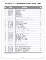
Page 18: ...E ASSEMBLY 1 U CLIP LINKAGE NAME PANEL SAFETY STRAP U SUPPORT SAFETY LATCH 1 4 20 X 1 1 2 HEX HEAD BOLT 10 24 X 3 4 PHILLIPS ROUND HD SCREW 2 CASTER CASTER SOCKET LEG CAP 1 1 2 OD 1 4 20 X 2 HEX HEAD...

Page 19: ...4 38 24 20 33 20 37 15 16 4 12 11 9 2 9 10 8 14 24 23 31 15 4 13 2 1 7 5 15 16 7 19 19 20 3 3 3 15 15 17 39 9 30 24 31 15 30 24 6 2 15 23 25 22 21 29 26 1 20 36 35 40 27 2L 4239 00 PARTS LIST ON PREVI...

Page 20: ...partes peque as pueden ser empacadas dentro de las partes grandes Verifique en el interior de todas las partes y cartones antes de ensamblar o solicitar partes 3 Para que el ensamblado le sea m s f ci...

Page 21: ...eparando sus tuercas y tornillos antes de empezar reducir el tiempo de instalaci n Separe las partes ahora para que este listo antes de empezar la instalaci n NOTA 8 x 1 7 16 Tornillo para lamina de m...

Page 22: ...artones del empaque donde ven a la mesa para proteger la superficie de la mesa pintada Aseg rese de que el tablero de la mesa est PRECAUCI N seguro sobre los caballetes y NUNCA deje la mesa sola Orifi...

Page 23: ...TED LE OCASIONARA DA OS IRREPARABLES A SU MESA CUANDO TRATE DE ABRIRLA EN LA POSICI N DE JUEGO PRECAUCI N Alinie los orificios de las abrazaderas en U 3 con los orificios peque os que est n de gu a en...

Page 24: ...montaje 33 y 34 con los orificios de gu a en el tablero e inserte los tornillos 20 como se muestra Todos los orificios en los Soportes 33 y 34 deben de alinearse con los orificios en el tablero Vea l...

Page 25: ...ra NECESITA 6 Abrazadera 6 Inserte los Tapones de las patas 13 a las Patas 2 como se muestra en la Figura 4 5 Instale las patas 2 al Soporte de Montaje 34 con el Tornillo de Cabeza Hexagonal 38 dos Ro...

Page 26: ...ranuras de las abrazaderas 3 donde van los tornillos Si es necesario deslice el soporte 7 de lado a lado para ver los orificios 7 Inserte el tornillo 19 a trav s de las ranuras de la abrazadera U 3 y...

Page 27: ...mo de cada Riel 25 y 29 como se muestra en el Detalle E1 E2 10 Alinie los orificios de los rieles con los orificios de gu a del tablero atornillelos y aseg relos con los dieciocho tornillos 20 Vea la...

Page 28: ...arte de ADENTRO de la pata 2 como est mostrada en el Detalle G2 Atornillelos en el ultimo orificio con el tornillo 23 el separador de pl stico 31 y la tuerca 15 Asegurese que las tuercas y tornillos e...

Page 29: ...toque el borde del tubo 17 Inserte las llantas 11 adentro del casquillo 12 Vea la Figura 7B NOTA NO GOLPEE EL CASQUILLO DIRECTAMENTE CON EL MARTILLO COLOQUE UN PEDAZO DE MADERA SOBRE EL CASQUILLO Y G...

Page 30: ...t n apretadas y seguras pero no las sobre apriete Los tubos deben girar libremente Vea la Figura 7C 19 Una la parte de abajo de la placa 5 a los soportes en forma de U 7 Atornillando los tornillos hex...

Page 31: ...ico 24 y las tuercas hexagonal 15 Vea la Figura 8 NOTA Apriete las tuercas de seguridad 15 nicamente con la mano Las quitara cuando los dos lados de las mesas sean unidas NOTA Apriete las tuercas de s...

Page 32: ...ablero contra de la primera mitad Remueva las tuercas de seguridad 15 de los tornillos 14 de la Segunda mitad donde el soporte en forma de U 7 y los Tubos Conectores 4 se unen Alinie los orificios de...

Page 33: ...del orificio sobre la Placa como est mostrado en las Figuras 10 11 y el Detall J Use uno de los tornillos 10 una rondana 17 y una tuerca hexagonal 16 NOTA EL BORDE DEL PASADOR DE SEGURIDAD DEBE IR EX...

Page 34: ...e la paleta de ping pong en el poste de la red como se muestra en el dibujo B 31 Inserte Deslizador de Seguridad en el canal del sostenedor de la paleta Vea el dibujo C Repita los pasos 29 al 31 para...

Page 35: ...seguridad 3 Repita los mismos pasos para la otra mitad de la mesa POSICI N PARA JUGAR SOLO POSICI N DE JUEGO POSICI N PARA GUARDAR AMBOS PASADORES ASEGURADOS PASADORES ASEGURADO Vea los dibujos detal...

Page 36: ...t a es aplicable para consumidores de la compra original de cualquier producto ESCALADE SPORTS en adelante denominado el Producto DURACI N DE LA GARANT A Se garantiza este Producto al comprador origin...

Page 37: ...EN U 1 TUBO CONECTOR PLACA TIRA DE METAL DE SEGURIDAD TUBO DE SOPORTE EN U PASADOR DE SEGURIDAD 1 4 20 X 1 1 2 TORNILLO DE CABEZA HEX 10 24 X 3 4 TORNILLO PHILLIPS LLANTA 2 CASQUILLO PARA LLANTA TAPAD...

Page 38: ...24 20 33 20 37 15 16 4 12 11 9 2 9 10 8 14 24 23 31 15 4 13 2 1 7 5 15 16 7 19 19 20 3 3 3 15 15 17 39 9 30 24 31 15 30 24 6 2 15 23 25 22 21 29 26 1 20 36 35 40 27 2L 4239 00 19 LISTA DE PARTES EN LA...

Reviews: