background image

Quantum Jazzy 1420 Series

  www.quantumrehab.com

                      17

Electronics Tray

The electronics tray is located  on the back of the power base. See figures 6 and 7. The ammeter, the charger power cord,
the main circuit breaker, the controller connector, and the charger fuse are all located on the electronics tray.

Ammeter (onboard charging system shown only): The ammeter displays the charger’s current output in amps. See VI.
“Batteries and Charging.”

Charger Power Cord (onboard charging system only): Connects the onboard charger to an electrical outlet for
battery charging.

Main Circuit Breaker: The main circuit breaker is a safety feature built into your power chair. When the batteries and the
motors are heavily strained (e.g., from excessive loads), the main circuit breaker trips to prevent damage to the motors and
the electronics. If the circuit trips, allow your power chair to “rest” for approximately one minute. Next, push in the circuit
breaker reset button, turn on the controller, and continue normal operation. If the main circuit breaker continues to trip
repeatedly, contact your authorized provider/specialist.

Controller Connector: This is where the controller connects to the power base. Each controller uses a different type of
cable. Regardless of which type of controller is used, the cable must be secured to the seat assembly and not allowed to
drag on the floor.

Charger Fuse (onboard charging system only): The charger fuse protects the ammeter from current overload. There
are three fuses on the electronics tray. The top one is the charger fuse. The bottom two are spares.

Active-Trac Suspension

The Quantum Jazzy 1420 is equipped with Active-Trac Suspension (ATS). ATS is a system designed to make the
power chair traverse different types of terrain and obstacles while maintaining smooth operation. With ATS, the front
anti-tip wheels work in conjunction with the motor suspension to help you maneuver over obstacles in excess of 2 in.
(5 cm) in height.

As the front anti-tip wheels come in contact with an obstacle, the front anti-tip wheel assembly is drawn upward. At the
same time, the motors are forced downward. This allows the motors to push the power chair over an obstacle without the
possibility of becoming “hung up.”

ATS also helps in day-to-day operating conditions. For instance, when you release the joystick, the power chair begins to
slow down.  As the chair slows down, the front anti-tip wheels will automatically drop toward the ground.  This will reduce
the forward tip that is typically encountered with mid-wheel drive chairs.

I I I .   Y O U R   P O W E R   C H A I R

Summary of Contents for Jazzy 1420 2HD

Page 1: ...ng Models Quantum 1420 4HD Quantum 1420 2SPHD Quantum 1420 2SPVHD Quantum 1420 3SPHD Quantum 1420 4SPHD Quantum 1420 3SPVHD Quantum 1420 3MPHD Quantum 1420 4MPHD Quantum 1420 3MPVHD Jazzy 1420 3VHD Ja...

Page 2: ...ual and on the power chair to identify warnings and important information Itisveryimportantforyoutoreadthemandunderstandthemcompletely WARNING Indicates a potentially hazardous condition situation Fai...

Page 3: ...ies www quantumrehab com 3 I INTRODUCTION 4 II SAFETY 6 III YOUR POWER CHAIR 14 IV ASSEMBLY DISASSEMBLY 19 V COMFORT ADJUSTMENTS 21 VI BATTERIES AND CHARGING 29 VII CARE AND MAINTENANCE 33 VIII WARRAN...

Page 4: ...move or renderinoperableorunsafeanyguards shields orothersafetyfeaturesofthisproduct fail refuse orneglecttoinstallany retrofit kits from time to time provided by Pride to enhance or preserve the safe...

Page 5: ...eb site at www pridemobility com From our home page select Owners Club to enter a page dedicated to current and potential Pride product owners You willgainaccesstointerviews stories recreationideas da...

Page 6: ...lneed somepractice Simplytakeyourtimeandyouwillsoonbeinfullandconfidentcontrolasyoumaneuverthroughdoorways on and off of elevators up and down ramps and over moderate terrain Belowaresomeprecautions t...

Page 7: ...er incline Takewideswingswithyourpowerchair sfrontwheelsaroundanytightcorners Ifyoudothat thepowerchair srear wheels will follow a wide arc not cut the corner short and not bump into or get hung up on...

Page 8: ...n freewheel mode while seated on it Ask an attendant for assistance if necessary WARNING Do not place your power chair in freewheel mode while on an incline or decline This could cause the chair to ro...

Page 9: ...now severe cold or heat while operating your power chair proceed to shelter at the earliest opportunity Thoroughlydryyourpowerchairbeforestoring charging oroperatingyourpowerchair PROHIBITED Operating...

Page 10: ...pe of lift elevation product Your power chair was not designed with such use in mind and any damage or injury incurred from such use is not the responsibility of Pride Motor Vehicle Transport Priderec...

Page 11: ...ttempt to lift or move a power chair by any of its removable parts including the armrests seat foot riggings controller and shrouds Preventing Unintended Movement WARNING If you anticipate being seate...

Page 12: ...chair seat to prevent the power chair from tipping forward during transfer WARNING Avoid putting all of your weight on the power chair armrests and do not use the armrests for weight bearing purposes...

Page 13: ...ceivers used by emergency vehicles In some cases thesewavescancauseunintendedmovementordamagetothecontrolsystem Everyelectrically poweredmobility vehiclehasanimmunity orresistance toEMI Thehighertheim...

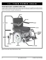
Page 14: ...rests seatback andseatbase Thepowerbaseassemblyincludestwomotor brakeassemblies twodrivewheels twoanti tip wheels twocasterwheels twobatteries andwiringharnesses SEATBACK CONTROLLER ARMREST BODY SHROU...

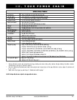
Page 15: ...tmounted MaximumSpeed Upto4 5mph 7 24km h Upto6mph 9 65km h withhigh speedmotors Range 1 Variableupto25miles 40km Brakes IntelligentBraking electronicregenerative discparkbrake GroundClearance 4 5in 1...

Page 16: ...OWER NOT SHOWN Figure 6 The Quantum Jazzy 1420 Series Power Base Shroud Removed FREEWHEELLEVER MAINCIRCUITBREAKER AMMETER CONTROLLER CONNECTOR CHARGERPOWERCORD Figure 7 The Quantum Jazzy 1420 Series E...

Page 17: ...uses a different type of cable Regardless of which type of controller is used the cable must be secured to the seat assembly and not allowed to drag on the floor Charger Fuse onboard charging system...

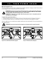
Page 18: ...WARNING It is important to remember that when your power chair is in freewheel mode the braking system is disengaged To operate the manual freewheel lever 1 Pullthemanualfreewheelleveroutandrotatecloc...

Page 19: ...cessarytoinstalltheseateitherpriortoinitialoperationoraftertransportingyourpowerchair Mostseatsare attachedtothepowerbasewiththeUniversalMountingSystem UMS TheUMSconsistsofuniversalpartsthatmaybe atta...

Page 20: ...nstalledinthearmrest WARNING Do not place the controller cable so that it can be pinched in the seat frame or power base frame 1 Flipupeithertherightorleftarmrest 2 On a contour seat flip up the armre...

Page 21: ...er chair WARNING Remove the occupant from the power chair before making any adjustments V C O M F O R T A D J U S T M E N T S Figure 12 Seat Latch Safety Disengaged Figure 13 Seat Height Adjustment QU...

Page 22: ...the seat 5 Repositiontheextrusionsonadifferentsetofmounting holes Youmustmovebothextrusionsthesamenumber ofholeseitherforwardorbackwards Seefigure14 6 Fastentheextrusionsbackontothebottomoftheseat 7 R...

Page 23: ...he other NOTE Changing the armrest width may increase the overall width of your power chair To change the armrest width 1 Locate the two armrest knobs on each side of the arm rest receiver bracket See...

Page 24: ...To change the controller position 1 Turn off the power to the controller 2 Disconnect the controller from the power base 3 Cut the wire tie s securing the controller cable to the armrest 4 Flip up the...

Page 25: ...tscrew to raise or lower the front of the foot platform Foot Platform Height Adjustment The foot platform height is easily adjusted to six different heights To raise or lower the foot platform 1 Use a...

Page 26: ...ng Leg Rests Optional Elevating Leg Rests ELRs offer an infinite range of ad justment for the leg angle and a footrest adjustment range of 12 19 in 30 5 48 26 cm See figure 19 To rotate the ELRs 1 Pus...

Page 27: ...igure 20 To change leg rest length A 1 Remove the hardware 2 Move the leg rest to the desired position 3 Reinstallthehardware To change foot plate position B 1 Remove the hardware 2 Move the foot plat...

Page 28: ...ide of the locknut 4 To adjust the anti tip upward turn the cam counterclockwise To adjust the anti tip downward turn the cam clock wise See figure 22 5 Tightenthelocknut NOTE Each drive tire must hav...

Page 29: ...tlet PROHIBITED Removal of grounding prong can create electrical hazard If necessary properly install an approved 3 pronged adapter to an electrical outlet having 2 pronged plug access PROHIBITED Neve...

Page 30: ...into the charger power cord receptacle on the power base then into the electrical outlet NOTE The power chair incorporates an inhibit function that disables the power chair when the charger is plugged...

Page 31: ...l day on a daily basis or you may not use it for weeks at a time Daily Use If you use your power chair on a daily basis charge the batteries as soon as you are finished using your power chair Your pow...

Page 32: ...and long life It will be well worth it to take the time to break in your battery properly How can I ensure maximum battery life Afully charged deep cycle battery will provide reliable performance and...

Page 33: ...take your power chair to an authorized provider specialist Power chairs that are frequently exposed to sources of water such as incontinence should be inspected often for corrosion and electronic comp...

Page 34: ...thatallpartsofthecontrollersystemaresecurelyfastenedtoyourpowerchair Donotovertightenanyscrews Check for proper tire inflation There should be 35 psi 2 4 bar in each tire If a tire does not hold air c...

Page 35: ...of power chair packaging metalframecomponents plasticcomponents electronics andbatteries Cleaning Instructions Useadampclothandmild non abrasivecleansertocleantheplasticandmetalpartsofyourpowerchair A...

Page 36: ...y 8 Reassembletherimsandreinstallthescrews 9 Slide the wheel back onto the axle 10 Reinstallthedrivewheelnutandwasherontotheaxleandtighten 11 Inflate the pneumatic tires to 35 psi 2 4 bar 12 Remove th...

Page 37: ...the rear battery WARNING Make sure you tighten the fasteners so that the connections are secure 11 Reinstall the shroud and trapeze bars 12 Reinstalltheseat 13 Plug in the connectors to the electronic...

Page 38: ...gging mounting brackets 18 MONTH LIMITED WARRANTY Foreighteen 18 monthsfromthedateofpurchase Pridewillrepairorreplaceatouroptiontotheoriginalpurchaser free of charge any of the following parts found u...

Page 39: ...t through heavy use is not covered SERVICE CHECKS AND WARRANTY SERVICE Warranty service must be performed by a authorized provider specialist Do not return faulty parts to Pride without prior writtena...

Page 40: ...40 www quantumrehab com Quantum Jazzy 1420 Series N O T E S...

Page 41: ...Quantum Jazzy 1420 Series www quantumrehab com 41 N O T E S...

Page 42: ...42 www quantumrehab com Quantum Jazzy 1420 Series N O T E S...

Page 43: ...Control Quantum Jazzy 1420 Series Inclusion of all Parts JoystickSerialNumber ControllerSerialNumber LeftMotorSerialNumber RightMotorSerialNumber Fit and Finish Performance Product Serial Pride keeps...

Reviews: