Repair and Testing Instructions for T1 Page 19
Alternator 0120 689 552
Edition 001
All rights rest with Robert Bosch Corp, including patent rights. All rights of use of reproduction and publication rest with R. B. Corp.
UA/ASV
04.12.98
T1ALTFinal.DOC
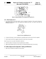
b. Using a Diode Tester
i) Connect the negative (black) lead of the tester to the collector end shield and the positive (red) lead
to each of the stator connection solder joints. No current should pass through the rectifier assembly.
ii) Connect the positive (red) lead of the tester to the collector end shield and the negative (black) lead
to each of the stator connection solder joints. Current should pass through the rectifier assembly.
iii) Connect the positive (red) lead of the tester to the B+ Terminal and the negative (black) lead to
each of the stator connection solder joints. No current should pass through the rectifier assembly.
iv) Connect the negative (black) lead of the tester to the B+ Terminal and the positive (red) lead to
each of the stator connection solder joints. Current should pass through the rectifier assembly.
v) Connect the positive (red) lead of the tester to the D+ Terminal and the negative (black) lead to
each of the stator connection solder joints. No current should pass through the rectifier assembly.
vi) Connect the negative (black) lead of the tester to the D+ Terminal and the positive (red) lead to
each of the stator connection solder joints. Current should pass through the rectifier assembly.
If the rectifier assembly fails any test, one or more of the diodes are defective and the whole assembly must be
replaced.
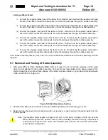
9.7 Removal and Testing of Stator Assembly
1. With tester WPG 012.00 or Multimeter MMD 302 set to read 0 to 0.5
W
, test the resistance of the stator
while it is still attached to the rectifier assembly. Connect the test leads between the phase outputs of the
stator. Repeat the test until all three phases of the stator has been tested. A good stator will read between
0.036
W
and 0.040
W
. (Figure 12)
2. Unsolder the stator phase connections from the rectifier assembly with a soldering gun or iron.
3. Bend open any bent-over lead connections with a screwdriver or pliers and pull the stator leads from the
rectifier eyelets.
Note: The insulation tester applies a voltage of 80 VAC to the stator. Voltages of 80V can be fatal.
When performing this test, observe care is used in handling the stator and any component or
surface that is exposed to the stator. Use insulated gloves and do not touch the work surface
until all tests are completed.
Figure 12 Stator Resistance Testing
Summary of Contents for LE MIRAGE XLII
Page 1: ...COACH MANUFACTURER MAINTENANCE MANUAL LE MIRAGE XLII BUS SHELLS PA1553 ...
Page 2: ......
Page 12: ...Section 00 GENERAL INFORMATION 10 PA1553 FIGURE 13 METRIC US STANDARD CONVERSION TABLE 00005 ...
Page 13: ...Section 00 GENERAL INFORMATION PA1553 11 FIGURE 14 CONVERSION CHART 00006 ...
Page 14: ......
Page 30: ......
Page 131: ...section01f tif 1700x2164x2tiff ...
Page 132: ...section01f tif 1700x2164x2tiff 2 ...
Page 133: ...section01f tif 1700x2164x2 3 ...
Page 134: ...section01f tif 1700x2164x2 4 ...
Page 135: ...section01f tif 1700x2164x2 5 ...
Page 136: ...section01f tif 1700x2164x2 6 ...
Page 137: ...section01f tif 1700x2164x2 7 ...
Page 138: ...section01f tif 1700x2164x2 8 ...
Page 139: ...section01f tif 1700x2164x2 9 ...
Page 140: ...section01f tif 1700x2164x2tiff 10 ...
Page 141: ...section01f tif 1700x2164x2tiff 11 ...
Page 142: ...section01f tif 1700x2164x2tiff 12 ...
Page 143: ...The ONLY Motor Coach Power Choice ...
Page 182: ......
Page 185: ...Section 04 EXHAUST SYSTEM PA1553 3 FIGURE 2 EXHAUST SYSTEM INSTALLATION W5 04013 ...
Page 206: ......
Page 207: ......
Page 208: ......
Page 209: ......
Page 210: ......
Page 211: ......
Page 212: ......
Page 213: ......
Page 214: ......
Page 278: ......
Page 328: ......
Page 345: ...FAULT CODE MANUAL Created on 00 04 25 15 30 1 FAULT CODE MANUAL B7L B7TL B12 ...
Page 370: ......
Page 397: ......
Page 398: ......
Page 399: ......
Page 400: ......
Page 401: ......
Page 402: ......
Page 403: ......
Page 404: ......
Page 405: ......
Page 406: ......
Page 407: ......
Page 408: ......
Page 425: ......
Page 492: ...Section 12 BRAKE AND AIR SYSTEM PA1553 20 FIGURE 38 AIR OPERATED BRAKING SYSTEM W0 WE ...
Page 493: ...Section 12 BRAKE AND AIR SYSTEM PA1553 21 FIGURE 39 AIR OPERATED BRAKING SYSTEM W5 ...
Page 500: ...Section 12 BRAKE AND AIR SYSTEM PA1553 28 FIGURE 46 ABS 4S 4M CONFIGURATION ...
Page 528: ...16 BW2158 Honeywell Commercial Vehicle Systems Company 4 2001 Printed in USA ...
Page 532: ......
Page 540: ......
Page 548: ......
Page 555: ......
Page 568: ......
Page 588: ......
Page 594: ......
Page 597: ......
Page 665: ......
Page 666: ......
Page 667: ......
Page 668: ......
Page 669: ......
Page 670: ......
Page 671: ......
Page 672: ......
Page 673: ......
Page 674: ......
Page 675: ......
Page 676: ......
Page 677: ......
Page 678: ......
Page 679: ......
Page 680: ......
Page 681: ......
Page 682: ......
Page 683: ......
Page 684: ......
Page 685: ......
Page 686: ......
Page 687: ......
Page 688: ......
Page 689: ......
Page 690: ......
Page 691: ......
Page 692: ......
Page 693: ......
Page 694: ......
Page 695: ......
Page 696: ......
Page 697: ......
Page 698: ......
Page 699: ......
Page 700: ......
Page 701: ......
Page 702: ......
Page 703: ......
Page 704: ......
Page 705: ......
Page 706: ......
Page 707: ......
Page 708: ......
Page 709: ......
Page 710: ......
Page 711: ......
Page 712: ......
Page 713: ......
Page 714: ......
Page 715: ......
Page 716: ......
Page 717: ......
Page 718: ......
Page 719: ......
Page 720: ......
Page 721: ......
Page 722: ......
Page 723: ......
Page 724: ......
Page 725: ......
Page 726: ......
Page 727: ......
Page 728: ......
Page 729: ......
Page 730: ......
Page 731: ......
Page 732: ......
Page 733: ......
Page 734: ......
Page 735: ......
Page 736: ......
Page 737: ......
Page 738: ......
Page 739: ......
Page 740: ......
Page 741: ......
Page 742: ......
Page 743: ......
Page 744: ......
Page 745: ......
Page 746: ......
Page 747: ......
Page 748: ......
Page 749: ......
Page 750: ......
Page 751: ......
Page 752: ......
Page 753: ......
Page 754: ......
Page 755: ......
Page 756: ......
Page 757: ......
Page 758: ......
Page 759: ......
Page 760: ......
Page 761: ......
Page 762: ......
Page 763: ......
Page 764: ......
Page 765: ......
Page 766: ......
Page 767: ......
Page 768: ......
Page 769: ......
Page 770: ......
Page 771: ......
Page 772: ......
Page 773: ......
Page 774: ......
Page 775: ......
Page 776: ......
Page 777: ......
Page 778: ......
Page 779: ......
Page 780: ......
Page 781: ......
Page 782: ......
Page 783: ......
Page 784: ......
Page 785: ......
Page 786: ......
Page 787: ......
Page 788: ......
Page 789: ......
Page 790: ......
Page 791: ......
Page 792: ......
Page 793: ......
Page 794: ......
Page 795: ......
Page 796: ......
Page 797: ......
Page 798: ......
Page 799: ......
Page 800: ......
Page 801: ......
Page 802: ......
Page 803: ......
Page 804: ......
Page 805: ......
Page 806: ......
Page 807: ......
Page 808: ......
Page 809: ......
Page 810: ......
Page 811: ......
Page 812: ......
Page 813: ......
Page 814: ......
Page 815: ......
Page 816: ......
Page 817: ......
Page 818: ......
Page 819: ......
Page 820: ......
Page 821: ......
Page 822: ......
Page 964: ......
Page 978: ......
Page 980: ......
Page 982: ......
Page 988: ......
Page 994: ......
Page 998: ......
Page 1002: ......
Page 1004: ...PROCEDURE NO PR00044 REVISION 00 Page 2 of 2 Slide out ...
Page 1008: ......
Page 1010: ......
Page 1012: ......
Page 1018: ......
Page 1022: ......
Page 1024: ......
Page 1032: ......
Page 1054: ......
Page 1066: ......
Page 1070: ......
Page 1074: ......
Page 1110: ......
Page 1116: ......
Page 1122: ......
Page 1142: ......
Page 1165: ...Section 22 HEATING AND AIR CONDITIONING PA1553 19 FIGURE 17 DOUBLE SWEEP EVACUATION SET UP ...
Page 1201: ...Section 22 HEATING AND AIR CONDITIONING PA1553 55 FIGURE 64 HEATER LINE SHUTOFF VALVES WE W0 ...
Page 1208: ......
Page 1209: ...Compressor 62 11052 Rev A WORKSHOP MANUAL for MODEL 05G TWIN PORT COMPRESSOR R ...
Page 1210: ...WORKSHOP MANUAL COMPRESSOR MODEL 05G TWIN PORT ...
Page 1233: ...Compressor 62 11053 Rev B SERVICE PARTS LIST for MODEL 05G TWIN PORT COMPRESSOR 1 2 3 4 5 6 R ...
Page 1261: ......
Page 1262: ......
Page 1263: ...1 ...
Page 1264: ...2 ...
Page 1265: ...3 ...
Page 1266: ...4 ...
Page 1267: ...5 ...
Page 1268: ...6 ...
Page 1269: ...7 ...
Page 1270: ...8 ...
Page 1271: ...9 ...
Page 1272: ......
Page 1294: ......
Page 1305: ...Section 26 XLII SLIDE OUT PA1553 11 ...
Page 1306: ...Section 26 XLII SLIDE OUT PA1553 12 FIGURE 16 KEYLESS BUSHING INSTALLATION INSTRUCTION ...

