PREVAC Sp z o.o., Raciborska 61 str. PL44362 Rog
ów
Tel.: +48 32 45 92 000, Fax: +48 32 45 92 001, e-mail:
prevac
@prevac.eu
, http://www.prevac.eu
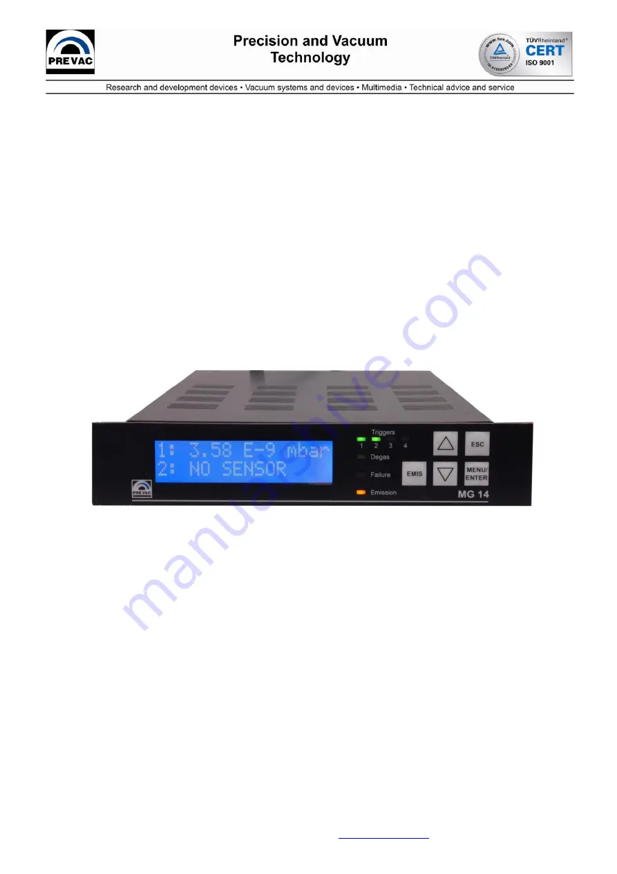
Ionization Multi Gauge
Controller MG14
Operating Manual
Software version: v7.0
Rev 1.4
January 2016
Page 1: ...o Raciborska 61 str PL44362 Rogów Tel 48 32 45 92 000 Fax 48 32 45 92 001 e mail prevac prevac eu http www prevac eu Ionization Multi Gauge Controller MG14 Operating Manual Software version v7 0 Rev 1 4 January 2016 ...
Page 2: ...NECTION 8 2 3 CHANNELS 8 2 3 1 SENSOR CONNECTIONS 8 2 3 2 SENSOR SUPPLY 9 2 3 3 MEASURING RANGES 9 2 3 4 MEASURING TECHNIQUE 10 2 4 INTERFACES 10 2 4 1 RELAY OUTPUTS 10 2 4 2 I O OUTPUTS 10 2 4 3 COMMUNICATION INTERFACES 11 3 INSTALLATION 12 3 1 UNPACKING 12 3 2 MECHANICAL INSTALLATION 12 3 2 1 DESK TOP DEVICE 12 3 2 3 RACK INSTALLATION 13 3 2 4 INTERFACE MODULE MOUNTING 14 3 3 CONNECTING 16 3 3 1...
Page 3: ... 1 CUSTOMER MENU CUSTOMER 39 4 2 13 1 SERVICE MENU SERVICE 39 4 2 14 1 INFORMATION MENU INFORMATION 39 5 MAINTENANCE AND SERVICE 39 5 1 MAINTENANCE 39 5 1 1 CLEANING 39 6 STORAGE AND DISPOSAL 41 6 1 PACKAGING 41 6 2 STORAGE 41 6 3 DISPOSAL 41 7 APPENDINX 42 7 1 TROUBLE SHUTTINGS ERROR MASSAGES 42 7 2 INDEX 44 8 WARRANTY CONDITIONS 46 8 WARRANTY CONDITIONS 46 DECLARATION OF CONFORMITY 47 ...
Page 4: ...uge MG14 will be referred to as MG 14 1 2 LIABILITY AND WARRANTY PREVAC Sp z o o assumes no liability and the warranty becomes null and void if the end user or third parties Disregard the information in this document Use the product in a non conforming manner Make any kind of alterations modifications repair work etc to the product Use the product with accessories not listed in the corresponding p...
Page 5: ... damage NOTE Indicates particularly important but not safety relevant information 1 4 3 General Safety Instructions For all work you are going to do adhere to the applicable safety regulations Also observe all safety notes given in this document and forward the information to all other users of the product In particular pay attention to the following safety notes DANGER Mains voltage Contact with ...
Page 6: ...evice dry WARNING Improper use Improper use can damage the MG14 Use the MG14 only as intended by the manufacturer WARNING Improper installation and operation data Improper installation and operation data may damage the MG14 Strictly adhere to the stipulated installation and operation data ...
Page 7: ...sions in mm 2 1 2 Ambience Temperature Storage 40 70 C Operation 5 50 C Relative humidity Max 75 up to 32 C decreasing to max 50 above 45 C Use Indoors only Altitude max 2000 m NN Pollution degree II Protection type IP20 2 1 3 Operation Manually Via 5 control buttons on the front panel Remote control Via RS232 RS485 USB CAN BUS PROFI BUS EthernetIP this has to be chosen with order or can be implem...
Page 8: ...00 6 3 Electromagnetic compatibility generic immunity standard 2 2 Mains Connection Voltage 90 250 VAC Frequency 50 60 Hz Current consumption Max 3 5 A at 115 V Max 1 75 A at 230 V Power consumption Max 250 W Overvoltage category II Protection class 1 Connection European appliance connector IEC 320 C14 Fuse 3 5 A in power supply 2 3 Channels 2 3 1 Sensor Connections Channel 1 Sensor connections UT...
Page 9: ...ol Anode potential Reflector potential Cathode potential Emission current Power Degas timer 500V 90V max 80 mA adjustable max 40W adjustable 1 20 min 480V 20V max 80 mA adjustable max 40W adjustable 1 20 min 480V 205V 10V max 80 mA adjustable max 40W adjustable 1 20 min 1 1 1 5 1 1 2 3 2 2 THERMOVAC CERAVAC and IONIVAC Transmitters Voltage 24 VDC 5 Current 0 1 A Thermovac Ceravac 1 2A IONIVAC ITR9...
Page 10: ...100 fA 1 25 s 1 100 fA 2 5 s 1 Channels 2 transmitters Entire range 20 s 1 Display rate temperature drift unit of measurement Display rate 4 s 1 Temperature drift 0 1 per C Unit of measurement mbar Pa Torr Micron Resolution of the A D converter THERMOVAC CERAVAC and IONIVAC bit Extractor B A Gauge bit 2 4 Interfaces 2 4 1 Relay Outputs Name Relay Connection D Sub 9 pins female See Fig 3 8 Number o...
Page 11: ...sparent interface Bluetooth class 2 SPP compatible Wireless range up to 30 meters RS 232 Passive module with serial application interface Physical layer converter for the RS 232 communication standard Supports baud rates up to 250 kbit s No configuration necessary since the module acts only on the physical layer RS 485 Passive module with serial application interface Physical layer converter for t...
Page 12: ...ation Secure the damaged product from unintended operation Send a damage report to the haulage company or the insurer 3 2 Mechanical Installation The MG14 can be used as follows As a desk top device mounted in a control panel or mounted in a 19 rack In each of these cases you must pay attention to the following safety note WARNING Ambient temperature Exceeding the maximum permitted ambient tempera...
Page 13: ... order to use MG14 in the rack there is necessary to remove four stuck gummy legs For this purpose proceed as follows 1 Switch off the MG14 and disconnect it from mains power 2 Turn the MG14 upside down as shown in Fig 3 1 3 Remove unstuck the four stuck gummy legs 4 Turn the MG14 back to normal orientation and place it on the required location Fig 3 1 Unstuck gummy legs from the device NOTE In or...
Page 14: ... any time on request For the proper installation please follow the instruction CAUTION Turn the unit off Before proceed with any modules ensure that the main power is off This prevents any electric damages in the unit CAUTION Screws fully loose Before inserting the module ensure that the affixing screws have been fully loosened ...
Page 15: ...To be sure if the module is mounted correctly please have a look into the unit via the holes as shown on the photo Fig 3 3 Fig 3 3 Anybus Module mounting 1 When inserting the module into the slot press it with its plain side onto the MG14 board 2 Tighten the affixing screws until they make contact with the panel ref 3 The affixing screws lock the module in place in the slot ...
Page 16: ...ternal protective conductor The internal protective conductor is connected to the casing with a screw Do not turn or loosen this screw The configuration of the available connections is described in the following sections 3 3 2 Mains Connection The mains connection Fig 3 4 item G is designed for a mains cable which contains a European appliance connector on the device side A mains cable is supplied...
Page 17: ... the mains connection of the device 2 Connect the plug of the mains cable with the wall socket NOTE If the device is installed in a switching cabinet the mains power can be supplied via a switchable central power distributor 3 3 3 Ground The ground screw Fig 3 4 item B can be used to connect the MG14 with the protective ground of the pumping station If required Connect the protective ground of the...
Page 18: ...azardous voltage As soon as the emission is switched on both appliance plugs carry hazardous levels of voltage even if only one measuring system is connected The device must be switched off before any work is performed to the sensor or the measuring line After switching off wait approx 15 seconds before starting the work Measuring signals The measuring signals i e the ion currents of each sensor a...
Page 19: ...K 7 ITR Degas 8 ITR emission ON OFF n c not connected CAUTION Improper transmitter Transmitters which are not designed for use with the MG14 may damage the device Operate the MG14 with proper transmitters only See Chapter 2 3 1 Sensor Connections CAUTION Multiple connection Only one transmitter may be connected to each of the channels Otherwise the connected transmitters will be damaged Never conn...
Page 20: ...ger 1 NC 3 Trigger 1 NO 4 Trigger 2 common COM 5 Trigger 2 NO 6 Trigger 3 common COM 7 Trigger 3 NO 8 Trigger 4 common COM 9 Trigger 4 NO COM common NC normally closed NO normally open 3 3 8 Anybus module User has possibilities to operate the unit via one of the Anybus module for exact type please refer to the chapter 2 4 2 For exact module description and the pin assignment please refer to the ex...
Page 21: ...ils are shown in tab bellow Vacuum range measurement Torr Output voltage Uout V Logical status on outputs Preamplifier Range1 Preamplifier Range2 Preamplifier Range3 P Uout 4x10⁵x Sg x Ie 0 092 10 1 0 0 P Uout 4x10⁸x Sg x Ie 0 092 10 0 1 0 P Uout 4x10⁹x Sg x Ie 0 800 10 0 0 1 P Uout 4x10¹¹x Sg x Ie 0 000 10 0 0 0 where P pressure Uout Output voltage proportional to the Ion current Sg sensitivity f...
Page 22: ...ut for Channel 1 converted linear signal 13 Analogue out for Channel 2 non converted direct from the gauge 14 Digital Out OC type Failure signal 15 24VDC max 0 4A the serial interface of the computer with the RS232 connection Use a shielded cable NOTE All outputs are not isolated ...
Page 23: ... signal by blinking red Failure LED and additionally corresponding message to the failure is display on the LCD screen 4 1 1 3 Measurement Display The both channels measurement can be displayed digitally item C and as a bar graph for each channel separately Digital display The measurement is displayed as a three digit floating point number in scientific notation The unit of measurement is displaye...
Page 24: ...ns used for user interface related to the alphanumeric display EMIS initialization of ion gauge emission Up Down buttons move between the options ESCape button back to previous option or cancel from the current operation MENU ENTER this button has double meaning a get into the Main Menu mode b choice acceptation if it is requested 4 2 1 Menus To get into main menu push the ENTER MENU button once T...
Page 25: ...MG14 operating manual Rev 1 4 25 Fig 4 2 MENU tree ...
Page 26: ...c with below option ref to 4 2 1 4 Relays descriptions COM common contact NO Normal Open contact NC Normal Close contact Refer to chapter 3 3 6 to configure connections During the normal operation press MENU ENTER button than press again to get into the triggers menu The following switching function parameters are available Triggers Sets Triggers Logic Triggers Hysteresis 4 2 1 2 Trigger s Menu Tr...
Page 27: ...U ENTER button on active position left narrow you get into the next submenu when you define which channel actual trigger should be related to Fig 4 5 Triggers channel sets To change channel use narrow buttons or accept the choice pressing MENU ENTER button Then you get into the next submenu when you can define setpoint value Triggers Sets value on Fig 4 3 Fig 4 6 Triggers Setpoint HIGH menu Using ...
Page 28: ...ers Active All triggers can be activated or deactivated When the setpoint is active works exactly according to the setpoint values and logic Inactivation means completely switched off Fig 4 8 Triggers logic setting Using the narrow buttons or and MENU ENTER button you can change triggers activation E g in Fig 4 8 trigger T1 is active and T2 is inactive 4 2 2 1 Display mode menu During the normal o...
Page 29: ... as shown on Fig 4 11 This opportunity is really useful for long distance waching when digits are not big enough Fig 4 11 Gross Mode Display 4 2 3 1 Units menu UNITS In this menu there is possible to define unit of measurement for pressure values displayed for each channel separately Using the narrow buttons or and MENU ENTER button you can move between option and confirm current choice The unit a...
Page 30: ...ers There is an individual set of Bayard Albert ionization sensor Such a possibilities makes MG14 flexible unit and can be customized to most Bayard Alpert existing on the market Using the narrow buttons or and MENU ENTER button you can move between the parameters and set the values 4 2 4 3 Emission current menu EMIS CURR The following emission current for B A gauge can be choose 0 1 1 99 mA adjus...
Page 31: ...t relatively high pressure levels can damage the sensor Only set the emission current to a fixed value if you can be sure that the sensor will operate at sufficiently low pressure levels 4 2 4 4 Sensitivity factor menu SENSITI CALIB for extractor IE514 515 Function describing relation between gas type the geometry of the gauge and the absolute temperature is generally defined as gauge sensitivity ...
Page 32: ... referring to the serial number of EXTRACTOR gauge 4 2 4 7 Filament selection menu FILAMENT Most of available B A gauges have two filaments In this menu this selection is possible gauge will operate on the filament which has been set in this menu Also degas procedure operates with this filament NOTE EXTRACTOR IE514 515 and B A IE414 415 gauges have only one filament installed In case of switch to ...
Page 33: ... if ITR091 or ITR100 is set on this channel During degassing pressure measurements cannot be performed The measurement display shows the Degasing command The degas function is switched off automatically after the time declared in next submenu see chapter 4 2 5 3 You may also deactivate this function manually at any time by pressing MENU ENTER button again During degassing procedure yellow LED on t...
Page 34: ...ission of B A gauge on channel 1 or emission of ITR091 ITR100 on channel 2 can be activated automatically according to the interlocks Automatic emission can be allocated to the on of four triggers as shown on the Fig 4 16 Fig 4 16 Emission control menu Explanation of Fig 4 16 is as follows emission of B A gauge is related to the Trigger 3 automatic on when Trigger 3 value is reached see chapter 4 ...
Page 35: ...urrent SN2 gauge sensitivity for N2 Rg gas correction factor The gas type correction becomes a function of the pressure if the pressure exceeds 0 5 mbar This fact is taken into consideration for all gas types that can be selected The following gas type correction factors are implemented and can be choose using the narrow buttons or and MENU ENTER button for each channel separately Gas Rg He 0 18 N...
Page 36: ...vary significantly between seemingly identical gauges and even more for different gauge types filament materials and operating potentials For general vacuum use the discrepancy in reported measurements is not greater than 10 for the common gauges rising to a little above 20 for the less common gases where less accurate information is available ...
Page 37: ...fter power off 4 2 10 1 Display parameters menu Display param LCD display is controlled by microcontroller and backlight of it as well Because of different angle of few it is possible to set individual brightness and contrast of LCD display Fig 4 17 Fig 4 17 Display menu Using the narrow buttons or and MENU ENTER button you can change the value of brightness and contrast from 0 100 As an additiona...
Page 38: ...nfigured in PARAMETERS submenu 4 2 11 2 EtherNet IP parameters Getting into this menu the following four parameters must be set IP Address this is typical IP address which will be related to current unit only in the network xxx xxx xxx xxx Subnet Mask set subnet mask address xxx xxx xxx xxx Gateway Gateway address xxx xxx xxx xxx DHCP enable or disable Dynamic Host Configuration Protocol Status Re...
Page 39: ...er This menu allows to enter customer name up to 12 characters This name is displayed later on in the network either website of the unit It allows for the unique unit identification if more than one of units are connected to the network 4 2 13 1 Service menu Service This menu is intended for manufacturer services only and can be activated only with the correct password 4 2 14 1 Information menu In...
Page 40: ...ng manual Rev 1 4 40 Mains voltage Components inside of the IM 540 are components to mains voltage Do not insert any objects through the louvers of the device Protect the device from liquids Do not open the device ...
Page 41: ...ervice center 6 2 Storage The MG14 may only be stored in a dry room The following requirements must be met Ambient temperature 20 60 C Humidity as low as possible Preferably in an air tight plastic bag with a desiccant 6 3 Disposal The product must be disposed of in accordance with the relevant local regulations for the environmentally safe disposal of systems and electronic components ...
Page 42: ...off let the device cool down check if louvers of the device are not locked be sure that air flow around device is proper check inside cabinet temperature if device is mounted in the rack 5 CATHODE OPEN No current in cathode circuit check gauge filament if is not open check gauge connection exchange gauge cable turn emission on again 6 CATHODE SHORT Current in cathode circuit too high Emission curr...
Page 43: ...han 10 turn the device off wait 10s and turn device on again 10 12V FAILURE 12V supply voltage different more than 10 turn the device off wait 10s and turn device on again 11 12V FAILURE 12V supply voltage different more than 10 turn the device off wait 10s and turn device on again ...
Page 44: ...r 32 Degas time 34 Degassing 9 Device 13 Digital display 24 Dimensions 7 Directive 8 Display 24 Display mode menu 29 Display parameters 37 Disposal 41 Dual mode 29 E Emission Control 34 Emission current 31 EtherNet IP 38 EtherNet IP parameters 38 F Filament current 31 Filament selection 33 Filament voltage 31 Front Panel 24 G Gas type 35 Gas type correction 35 Gauge parameters 31 Graph 24 Gross mo...
Page 45: ...485 connection 17 RS485 7 38 S Safety 5 Safety 4 Save Load 3 37 38 Sensitivity 32 Sensitivity factor 32 Sensor 30 Sensor Connections 8 Sensors 35 Service menu 39 Setpoint triggers 24 27 28 Standards 8 48 Storage 41 T Transmitter selection 33 Transmitters 2 9 20 Trigger 27 Triggers Logic 29 Triggers Sets 2 27 28 Trouble shuttings 42 U UART 12 21 Units 30 Unpacking 2 13 USB 3 7 12 21 38 39 Use 7 W W...
Page 46: ...f company PREVAC customer can hire specialist that can repair particular damage For replaced or repaired part PREVAC gives warranty for the period from 1 year since repair that part on the spot by customer Company PREVAC obliges itself to material responsibility for defects or incorrect functioning of device up to value that not exceeds price including transport of faulty part Covering consigned t...
Page 47: ...elating to electromagnetic compatibility 89 336 EEC Product Multi gauge controller MG14 Standards Harmonized and international national standards and specifications EN 61010 1 Safety requirements for electrical equipment for measurement control and laboratory use EN 61000 6 2 Electromagnetic compatibility generic emission standard EN 61000 6 3 Electromagnetic compatibility generic immunity standar...