PRESONUS CDL Series Owner'S Manual Download Page 18

3 Hookup 

3.2 

Onboard Performance Monitoring

CDL-series 

Owner’s Manual

14

3.2 

Onboard Performance Monitoring

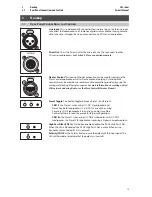
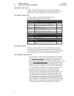
Performance Monitoring. These six LEDs display the 
performance status of the internal amplifier:

•  TEMP. The LED will illuminate when the internal temperature of the amplifier 

module has exceeded the recommended operating limit (64˚ C).

•  SIG. This LED illuminates when the input signal exceeds -50 dB. 
•  -3 dB. When this LED illuminates, the input signal has exceeded 

-3 dB, and you are in danger of clipping the ADC.

•  LIM. The protection limiter has been engaged when this indicator illuminates.
•  CLIP. The clip LED illuminates when the input signal has 

exceeded 0.5 dBFS, and the ADC is clipping, or when the amplifier 
exceeds the maximum upper limit (load dependent).

•  NET. This LED has three states:


Solid Red. Network not available.


Solid Blue. Network available.


Flashing Blue. Network packets are being sent or received.

Power User Tip:

 Never run your input levels higher than the channel 

inputs can handle. If you overdrive the A/D converters, it will cause 
digital distortion (digital clipping), which sounds terrible.

3.3 

Power

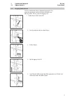
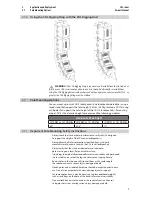
AC Line Connection. CDL-series loudspeakers have a universal power supply that 
accepts AC power input between 100 and 250 VAC at 50/60 Hz. Each loudspeaker is 
supplied with an AC powerCON® power cord appropriate for the country of sale.

WARNING:  Do not remove the center grounding prong or use a ground-
lift adapter, as this could result in electric shock.
WARNING:  Connect the powerCON connector on the AC powerCON 
power cord to the AC In connection on the amplifier 

before

 connecting 

the IEC connection to the AC mains power source. 

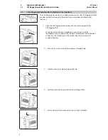
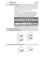
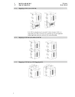
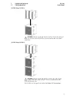
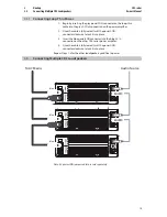
Power Thru. CDL-series loudspeakers provide loop-thru power. Using 
powerCON® Loop-thru cables and an AC powerCON Power cord, you can power 
up to six CDL-series loudspeakers on a single 15 amp / 120V (8 am / 240V 
electrical circuit. 
Loop-thru cable connectors are color coded as follows:


Blue. 

AC In.


Grey

AC Out. 


Power Switch. This is the On/Off switch. 
Power User Tip:

 If connecting multiple loudspeakers to the same 

electrical circuit, make sure that adequate line current is available. 
Maximum current draw for each CDL-series loudspeaker is 5.45 Amps. 

WARNING:  The power switch does not cut AC mains power from the 
loop-thru cables. If AC mains power is connected to one CDL-series 

loudspeaker, electrical power will be present on all connected loop-thru 
cables.

POWER

On/Off

Summary of Contents for CDL Series

Page 1: ...CDL series Constant Directivity Loudspeakers Owner s Manual www presonus com English...

Page 2: ......

Page 3: ...Rigging a CDL18s to a CDL Rigging Grid 8 2 7 6 Using the CDL Rigging Sling with the CDL Rigging Grid 9 2 7 Pole Mounting Options 9 2 7 1 Important Pole Mounting Safety Instructions 9 2 7 2 Pole Mount...

Page 4: ......

Page 5: ...regarding this product PreSonus Audio Electronics is committed to constant product improvement and we value your suggestions highly We believe the best way to achieve our goal of constant product imp...

Page 6: ...Rigging Extension Bar CDL Rigging Sling 1 5 Downloads Once you register your CDL series loudspeaker at My PreSonus com you will be able to download Worx Control software This application allows you to...

Page 7: ...are properly aligned for box to box vertical arraying If loudspeakers are not properly aligned physical damage and personal injury may occur The top of each loudspeaker should be parallel to the botto...

Page 8: ...be trained for loudspeaker rigging and mounting Make sure that all relevant health and safety regulations are known are followed by the installation crew and are in compliance with applicable local la...

Page 9: ...ins The integrated rigging pins function the same whether you are attaching CDL12 CDL18s or the CDL Rigging Grid 1 Rotate the pin to the forward 90 2 Press the release button to unlock the pin 3 Pull...

Page 10: ...lign the CDL Rigging Extension Bar with the center support of the CDL Rigging Grid For downward tilt the bar should be mounted at the rear of the loudspeaker array For upward tilt the bar should be mo...

Page 11: ...pported configurations below can lead to serious damage injury or death PreSonus has tested the configurations below for safety Please note that the structure from which you are suspending any CDL ser...

Page 12: ...2 to a CDL18s Note CDL12 loudspeakers must be mounted to the bottommost CDL18s in a suspended vertical array A CDL12 can be mounted atop a CDL18s for ground stacked applications only See Section 2 8 f...

Page 13: ...Important Pole Mounting Safety Instructions Always check the stand or pole specification to verify that it is designed to support the weight of the CDL series loudspeaker s Always observe all safety p...

Page 14: ...e socket 3 If mounting 2 CDL12 loudspeakers on one pole place the lower loudspeaker on the pole first then rig the top one to it following the instructions in Section 2 7 1 Important Use proper liftin...

Page 15: ...8s to the bottom of the CDL12 cannot exceed 40 PreSonus recommends the K M 21339 000 55 Crank Stand 1 CDL12 Atop 2 CDL18s WARNING Maximum pole height from the top of the upper CDL18s to the bottom of...

Page 16: ...0 55 Crank Stand The 2 CDL12 must be rigged to one another See Section 2 3 1 for instructions 2 8 Ground Stacking For ground stacking applications up to 2 CDL12 loudspeakers can be mounted atop up to...

Page 17: ...y using the mating male locking Ethernet connector For more information on creating a wired LAN network and using Dante see the Worx Control Reference Manual PresetToggle This button toggles between P...

Page 18: ...3 Power AC Line Connection CDL series loudspeakers have a universal power supply that accepts AC power input between 100 and 250 VAC at 50 60 Hz Each loudspeaker is supplied with an AC powerCON power...

Page 19: ...seated twist the powerCON connector clockwise to lock it into place 3 Insert the blue powerCON connector into the blue AC In connection on the other CDL series power amplifier 4 Once the cable is full...

Page 20: ...ill need to purchase a managed switch and dive into its configuration settings Select the port to which you ve connected your wireless router and set Multicast Filtering to On This will stop the flow...

Page 21: ...Limiter Clip NetworkStatus Enclosure 15mmEucalyptusplywood Mounting Dual positionpolemount 0 and10 IntegratedRigging 10 1load Dimensions HxWxD 18 6 x20 8 x17 5 473mmx529mmx444 5mm Weight 65 29 5kg Op...

Page 22: ...al Drawings 5 2 1 CDL12 529 mm 20 827 473 07 mm 18 625 80 121 20 mm 4 772 193 84 mm 7 631 126 84 mm 4 994 446 36 mm 17 573 325 56 mm 12 817 102 18 mm 4 023 80 5 2 2 CDL18s 529 mm 20 827 590 mm 23 228...

Page 23: ...Sonus Cost of Coverage Provided at no additional cost Included at no additional cost Who to contact to make a claim The seller PreSonus technical support for your region What This Warranty Covers PreS...

Page 24: ...ur sole and absolute option products covered by this warranty at no charge for labor or materials If the product must be shipped to PreSonus for warranty service the customer must pay the initial ship...

Page 25: ...xclusion of Damages PRESONUS S LIABILITY FOR ANY DEFECTIVE PRODUCT IS LIMITED TO THE REPAIR OR REPLACEMENT OF THE PRODUCT AT PRESONUS S SOLE OPTION IF PRESONUS ELECTS TO REPLACE THE PRODUCT THE REPLAC...

Page 26: ......

Page 27: ...ttle light beer 2 bay leaves 1 tsp thyme 2 lbs Redfish fillets Cooking Instructions 1 In a heavy saucepan or large skillet heat oil on medium high and slowly add flour a tablespoon at a time to create...

Page 28: ...Part 70 32000089 B 18011 Grand Bay Ct Baton Rouge Louisiana 70809 USA 1 225 216 7887 www presonus com CDL series Constant Directivity Loudspeakers Owner s Manual...

Reviews: