


4
remier
remier
roducts
roducts
P
P
P
P
WATER TREATMENT
®
Automatic Water Filters
occurs, household plumbing system must be flushed
clean.
C. CONNECT ALL FITTINgS
(refer to previous page)
CAUTION: Care must be used when working with copper
tubing. Do not allow the flame from torch to contact any
portion of the Valve assembly.
1. Attach 3/4” drain line to drain elbow with insert and
nut.
2. Do not elevate the drain line over 5’ above the top of
the valve (8’ on municipal systems) or to exceed 25’ in
length at either height.
CAUTION: An air gap must be provided upon sewer
entry. (Conform to local plumbing and sanitation
codes and ordinances).
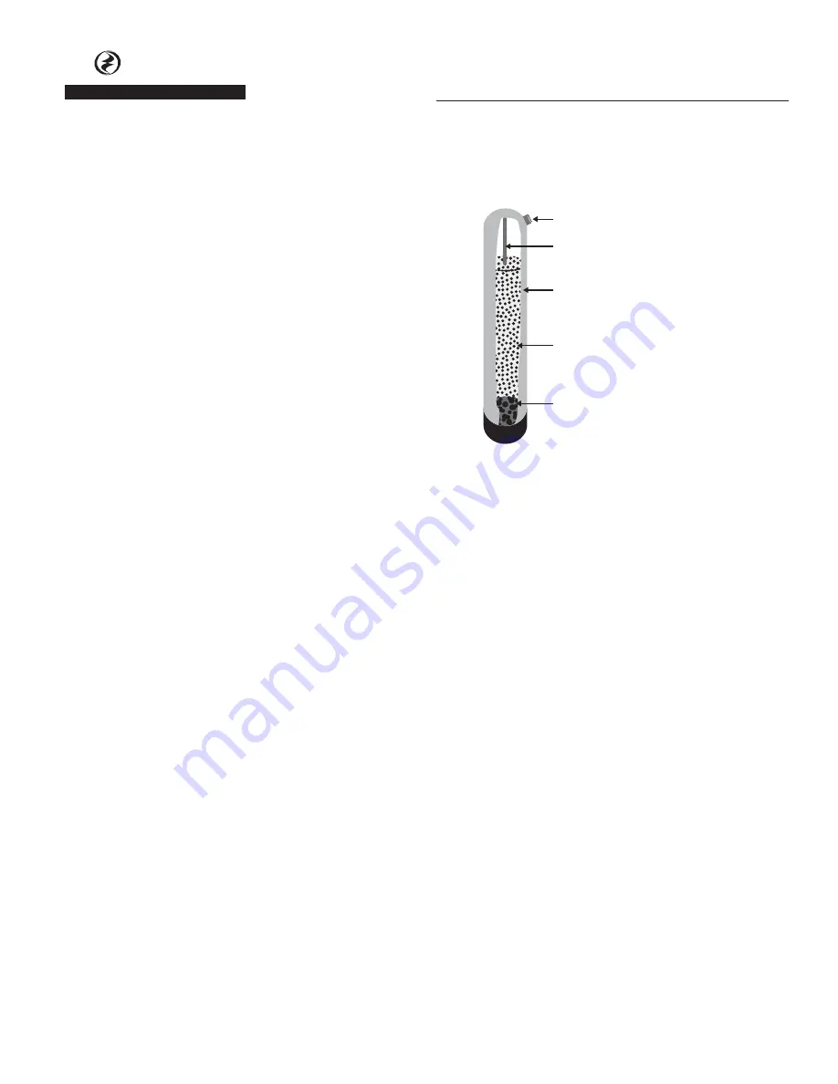
1. Media was shipped boxed under media tank.
Carefully unscrew control valve. Be sure to “plug” the
top of the distributor tube using tape or some other
means. Do not allow filter media to enter inside of
distributor tube. (See Fig. 3)
2. Pour the separately boxed media into media tank.
3. Lubricate o-rings on control valve with silicone
lubricant. DO NOT USE PETROLEUM JELLy.
4. Lubricate bypass valve o-rings with silicone lubricant
and secure to the control valve using adapter
couplings, clips and screws.
5. Cut main supply line as required to fit plumbing to
the inlet and outlet of bypass valve. Make certain
water flow enters through the Inlet and discharges
through the Outlet of the bypass valve.
6. Attach drain line to drain line fitting. Position drain
line over drain and secure firmly. To prevent back
siphoning, be sure to have adequate air gap of at
least 2 inches.
7. Make certain bypass valve is in the “bypass” position.
Turn on power to well pump or open main supply
valve completely.
8. Plug control valve into a non-switched 115v power
source.
9. Manually stage filter to the backwash position (see
service manual).
10. Open inlet valve and allow the unit to fill SLOWLY.
This will allow air to escape from the media tank.
Once water continually flows to drain, open both
inlet and outlet valves fully.
11. Check for leaks and allow filter to backwash for at
least 10 minutes or until water flowing from drain
runs clear.
12. Allow unit to fully regenerate (see service manual).
13. Models CBW10D, CBW20D, CCF10D and CCF20D have
a dome hole/plug located in the upper dome of the
mineral tank. This is used to replenish mineral as
required. DO NOT remove dome hole plug without
first depressurizing the tank.
Distributor Tube
Media Tank
Filter Media
Gravel - preinstalled
Dome Hole (”D” suffix models only)
INSPECTION AND HANDLINg yOUR FILTER
Be sure to inspect the equipment for shipping damage
and notify the transportation company if damage exists.
Handle the filter with care, as damage can result if
dropped or if the filter is set on a sharp object.
CONDUCT A THOROUgH WATER TEST
Your water should have a thorough analysis prior to the
selection of water conditioning equipment. Enter your
analysis below:
WATER ANALySIS
IRON (fe)
__________ ppm
Manganese (Mn)
__________ ppm
pH
__________
Tannins
__________ ppm
Hydrogen Sulfide (H2S) __________ ppm
NOTE: Hydrogen Sulfide must be tested at the well site.
Failure to conduct an “on site” analysis will result in
inaccurate test results.
LOCATINg EQUIPMENT CORRECTLy
The location of your filter should be selected carefully. A
variety of conditions will contribute to proper location as
follows:
1. Locate as close as possible to the source of water
supply.
2. Locate as close as possible to drain, i.e. laundry tub or
floor drain.