14
Packaged and Split Rooftop Ventilator
© 2021 Mitsubishi Electric US, Inc.
Premi
Sys
Alternate Supply Entry Locations
Each installation is unique and as a result, alternate
entry locations may be field-located. Before using any
alternate entry location, verify the suitability of the
location and ensure the use of an alternate location does
not interfere with unit wiring, components or functionality.
Recommended Electrical and Gas Supply
Entry Locations
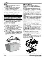
Manufacturer recommends that electrical service and
gas supply be brought into the cabinet through the end
wall, as shown below. There are three penetrations into
the cabinet that are required; one for high voltage supply
wiring, one for low voltage control wiring and one for
either gas supply or high voltage supply wiring for an
electric heater.
Recommended Gas and Electric Supply Entry Locations
Optional Unit
Disconnect
Field Wiring
Indirect
Gas
Supply
Location
Optional Gas Piping
Units with indirect gas-fired furnaces require field-
supplied and installed gas supply piping.
Typical Gas Supply Piping Connection
Ground
Joint
Union
8 in. Trap
Gas to
Controls
From Gas Supply
Bleeder Valve or
1/8 in Plugged Tap
Gas Cock
Gas Connections
If this unit is equipped with an indirect gas-fired furnace,
connection to an appropriate gas supply line will be
required. For complete information on installation
procedures for the optional gas furnace, refer the PVF/
PVG Indirect Gas-Fired Heat Module Installation,
Operation, and Maintenance Manual.
WARNING
Never drill holes in the roof of the unit! There is high
voltage wiring located between the inner and outer
roof panels. Damage to the wiring could cause severe
bodily harm or death.
NOTE
Housing size 5-1 gas furnaces are designed for gas
pressure of 5-13.5 in. wg for natural gas (6-inch
minimum on single 500 and 600 MBH furnaces) and
11-13.5 in. wg for LP. If the gas pressure at the job
location is greater than 13.5 in. wg, an additional
regulator is required to reduce pressure. For other
models, reference the Model PVF and PVG IOM.
Housing
Size
Total Heating
Capacity
(Input in MBH)
Gas
Connection
Size
Max Gas
Pressure
0-1
75
¾” NPT
14 in. wg.
100
150
200
1-1
100
¾” NPT
14 in. wg.
150
200
250
300
2-1
300
¾” NPT
14 in. wg.
400
500
4-1
600
¾” NPT
14 in. wg.
800
100
1” NPT
1200
5-1
600
1” NPT
13.5 in. wg.
800
2” NPT
1000
1200


