Premio RC0-6111E User Manual Download Page 105

RCO-

6100 Series  l  User’s Manual 

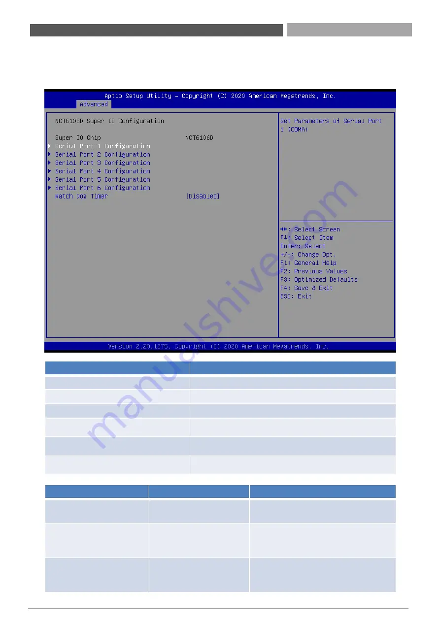
4.3.8  Super IO Configuration

This setting allows you to select options for the Super IO Configuration, and change the value of 
the selected option.

105

Chapter 4: BIOS Setup

Item 

Options 

Description 

Watch Dog Timer

Disabled 

[Default], 

Enabled

Enabled or Disabled Watch Dog Timer 
function.

Watch Dog Timer Count 

Mode

Second Mode

[Default]

,

Minute Mode

Select Second Mode or Minute Mode.

Watch Dog Timer Time out 

Value

20~255(Second)

[Default],

1~255(Minute)

Watch Dog Timer Time out Value.

Item 

Description 

Serial Port 1 Configuration

Set Parameters of Serial Port 1 (COMA). 

Serial Port 2 Configuration 

Set Parameters of Serial Port 2 (COMB). 

Serial Port 3 Configuration

Set Parameters of Serial Port 3 (COMC). 

Serial Port 4 Configuration

Set Parameters of Serial Port 4 (COMD). 

Serial Port 5 Configuration

Set Parameters of Serial Port 5 (COME). 

Serial Port 6 Configuration

Set Parameters of Serial Port 6 (COMF). 

Summary of Contents for RC0-6111E

Page 1: ...USER S MANUAL RCO 6100 Series Superior Fanless Embedded System...

Page 2: ...1 4L P RCO 6111 4L P M12 RCO 6111 D10G 16 1 3 3 RCO 6122 RCO 6122 4L P RCO 6122 4L P M12 RCO 6122 D10G 19 1 4 Mechanical Dimension 22 1 4 1 RCO 6100 RCO 6100 4L P RCO 6100 4L P M12 RCO 6100 D10G 22 1...

Page 3: ...87 3 16 Assemble PCIe PCI expansion module 89 3 17 Assemble chassis bottom cover 90 3 18 Installing SIM card 91 3 19 Installing wall mount kit 92 Chapter 4 BIOS Setup 93 4 1 BIOS Introduction 94 4 2...

Page 4: ...rt of this manual may be reproduced or transmitted in any form or by any means electronic or mechanical including photocopying recording or information storage and retrieval systems without the prior...

Page 5: ...o the power outlet Disconnect this equipment from the power before cleaning Use a damp cloth Do not use liquid or spray detergents for cleaning Avoid the dusty humidity and temperature extremes Do not...

Page 6: ...ion of your software operating system version application software etc A complete description of the problem The exact wording of any error messages Conventions Used in this Manual Preface This indica...

Page 7: ...th LGA 1151 for Intel 8th 9th Gen CPU Q370 PCH 2x LAN RCO 6100 4L Superior fanless embedded system with LGA 1151 for Intel 8th 9th Gen CPU Q370 PCH 6x LAN RCO 6100 4L M12 Superior fanless embedded sys...

Page 8: ...x16 Expansion RCO 6111E D10G Superior fanless embedded system with LGA 1151 for Intel 8th 9th Gen CPU Q370 PCH 2x LAN 2x 10G LAN 1x PCIe x16 Expansion RCO 6111P Superior fanless embedded system with L...

Page 9: ...Gen CPU Q370 PCH 2x LAN 4x PoE 2x PCI Expansion RCO 6122PP 4P M12 Superior fanless embedded system with LGA 1151 for Intel 8th 9th Gen CPU Q370 PCH 2x LAN 4x M12 PoE 2x PCI Expansion RCO 6122PP D10G...

Page 10: ...Chapter 1 Product Introductions...

Page 11: ...housing design and anti vibration RCO 6100 series are ruggedized systems that can operate in harsh environments and easy to install and maintain A build in over voltage protection OVP over current pr...

Page 12: ...e Support RAID 0 1 5 10 mSATA 1x mSATA Shared by 1x Mini PCI Express M 2 1x M 2 M Key NVMe PCIe x4 2280 1x M 2 E Key PCIe x2 USB 2 0 2230 SIM Socket 2x External SIM socket Expansion Mini PCI Express 2...

Page 13: ...SSD HDD port Removable 2 5 SATA HDD Bay support H 7mm hot swappable Support RAID 0 1 5 10 Internal 2 5 SATA HDD Bay support H 9mm Power LED Indicates the power status of the system HDD LED Indicates t...

Page 14: ...RCO 6100 Series l User s Manual 14 RCO 6100 RCO 6100 4L LAN Port RCO 6100 4P PoE Port RCO 6100 4L M12 M12 LAN Port RCO 6100 4P M12 M12 PoE Port RCO 6100 D10G D10G Port...

Page 15: ...output COM port COM1 COM2 support RS232 422 485 serial device DVI I port Used to connect a DVI monitor or connect optional split cable for dual display mode DisplayPort Used to connect a DisplayPort...

Page 16: ...port Removable 2 5 SATA HDD Bay support H 7mm hot swappable Support RAID 0 1 5 10 Internal 2 5 SATA HDD Bay support H 9mm Power LED Indicates the power status of the system HDD LED Indicates the stat...

Page 17: ...RCO 6100 Series l User s Manual RCO 6111 RCO 6111 4L LAN Port RCO 6111 4P PoE Port RCO 6111 4L M12 M12 LAN Port RCO 6111 4P M12 M12 PoE Port RCO 6111 D10G D10G Port 17 Chapter 1 Product Introductions...

Page 18: ...output COM port COM1 COM2 support RS232 422 485 serial device DVI I port Used to connect a DVI monitor or connect optional split cable for dual display mode DisplayPort Used to connect a DisplayPort...

Page 19: ...support H 7mm hot swappable Support RAID 0 1 5 10 Internal 2 5 SATA HDD Bay support H 9mm Power LED Indicates the power status of the system HDD LED Indicates the status of the hard drive Watchdog LE...

Page 20: ...RCO 6100 Series l User s Manual 20 RCO 6122 RCO 6122 4L LAN Port RCO 6122 4P PoE Port RCO 6122 4L M12 M12 LAN Port RCO 6122 4P M12 M12 PoE Port RCO 6122 D10G D10G Port Chapter 1 Product Introductions...

Page 21: ...output COM port COM1 COM2 support RS232 422 485 serial device DVI I port Used to connect a DVI monitor or connect optional split cable for dual display mode DisplayPort Used to connect a DisplayPort...

Page 22: ...RCO 6100 Series l User s Manual 22 1 4 Mechanical Dimensions 1 4 1 RCO 6100 RCO 6100 4L P RCO 6100 4L P M12 RCO 6100 D10G Chapter 1 Product Introductions Unit mm...

Page 23: ...RCO 6100 Series l User s Manual 23 Chapter 1 Product Introductions 1 4 2 RCO 6111E RCO 6111E 4L P RCO 6111E 4L P M12 RCO 6111E D10G RCO 6111P RCO 6111P 4L P RCO 6111P 4L P M12 RCO 6111P D10G Unit mm...

Page 24: ...1 4 3 RCO 6122EE RCO 6122EE 4L P RCO 6122EE 4L P M12 RCO 6122EE D10G RCO 6122PP RCO 6122PP 4L P RCO 6122PP 4L P M12 RCO 6122PP D10G RCO 6122PE RCO 6122PE 4L P RCO 6122PE 4L P M12 RCO 6122PE D10G Chapt...

Page 25: ...Chapter 2 Switches and Connectors...

Page 26: ...RCO 6100 Series l User s Manual 26 2 1 Switch and Connector Locations 2 1 1 Top View Chapter 2 Switches and Connectors...

Page 27: ...RCO 6100 Series l User s Manual 27 2 1 2 Bottom View Chapter 2 Switches and Connectors...

Page 28: ...pin DC 9 48V Power Input Connector DVI_I1 DVI I Connector MIC_IN1 Mic in Jack DIO1 8DI 8DO Connector PWR_SW2 PWR_SW3 Remote Power Switch CN1 M 2 E Key Socket CN2 M 2 M Key Socket MINIPCIE1 MINIPCIE2 M...

Page 29: ...s Manual 29 2 3 I O Interface Descriptions Pin Signal Pin Signal 1 3 3V 10 LPC_AD3 2 NC 9 LPC_AD2 3 Reset 8 LPC_AD1 4 LPC_FRAME L 7 LPC_AD0 5 Clock 6 GND 2 3 1 LPC Debug Con Chapter 2 Switches and Co...

Page 30: ...RCO 6100 Series l User s Manual 30 2 3 I O Interface Descriptions Pin Signal 1 5V 2 GND 3 GND 4 12V 2 3 2 Power Con Chapter 2 Switches and Connectors POWER1 1 4...

Page 31: ...RCO 6100 Series l User s Manual 31 2 3 I O Interface Descriptions Pin Signal 1 DC_IN 2 IGN_SENSE 3 GND 2 3 3 DC IN IGN IN 9V 48V Chapter 2 Switches and Connectors DC_IN1 1 3...

Page 32: ...8 RI 9 GND 10 NC 2 3 4 COM Con Chapter 2 Switches and Connectors COM5_1 COM6_1 Pin RS232 Definition RS422 485 Full Duplex Definition RS485 Half Duplex Definition 1 DCD TX DATA 2 DSR 3 RxD TX DATA 4 R...

Page 33: ...Definition RS422 485 Full Duplex Definition RS485 Half Duplex Definition 1 10 DCD TX DATA 2 11 RxD TX DATA 3 12 TxD RX 4 13 DTR RX 5 14 GND GND GND 6 15 DSR 7 16 RTS 8 17 CTS 9 18 RI Chapter 2 Switche...

Page 34: ...00 Series l User s Manual 34 2 3 I O Interface Descriptions Pin Signal Pin Signal 1 Power 3V 2 GND 3 CS 4 CLK 5 MISO 6 MOSI 7 NC 8 SPI_GATE 2 3 5 SF100 SPI Con Chapter 2 Switches and Connectors JP1 8...

Page 35: ...r 2 Switches and Connectors AT_ATX1 AT ATX Power Mode Switch Switch Definition 1 2 Left ATX Power Mode Default 2 3 Right AT Power Mode CAR_PWR1 PC Car Mode Switch Switch Definition 1 2 Left Power Mode...

Page 36: ...ptions Switch 1 2 3 Definition ON ON ON 3 sec Default Shutdown Timer by O S ON ON OFF 1 min ON OFF ON 5 min ON OFF OFF 10 min OFF ON ON 30 min OFF ON OFF 1 hour OFF OFF ON 2 hour Chapter 2 Switches an...

Page 37: ...Definition 1 GND 2 OUT_R 3 GND 4 GND 5 OUT_L Chapter 2 Switches and Connectors LINE_OUT1 Line out Jack Green Connector Type 5 pin Phone Jack Pin Definition 1 GND 2 MIC_R 3 GND 4 GND 5 MIC_L MIC_IN1 M...

Page 38: ...terface Descriptions Chapter 2 Switches and Connectors PWR_SW1 Power Button Pin Definition Pin Definition 1 NC 4 GND 2 Power Button 5 NC 3 NC 6 GND CLR_CMOS1 Clear BIOS Switch Switch Definition 1 2 Le...

Page 39: ...nterface Descriptions Chapter 2 Switches and Connectors Pin Definition 1 2 RESET 3 4 GND RESET1 Reset Button USB3_1 USB3 1 Connector Type A Pin Definition Pin Definition 1 5V 6 USB3_RX 2 USB2_D 7 GND...

Page 40: ...40 2 3 I O Interface Descriptions Chapter 2 Switches and Connectors 2 1 10 9 CN7 USB3 0 Connector 2x5 9 pin header 2 0mm pitch Pin Definition Pin Definition 1 5V 2 USB3_TX 3 USB2_D 4 USB3_TX 5 USB2_D...

Page 41: ...User s Manual 41 2 3 I O Interface Descriptions Chapter 2 Switches and Connectors CN6 USB3 1 Connector Type A x 4 Pin Definition Pin Definition 1 5V 6 USB3_RX 2 USB2_D 7 GND 3 USB2_D 8 USB3_TX 4 GND 9...

Page 42: ...O Interface Descriptions Chapter 2 Switches and Connectors Pin Definition Pin Definition C1 UIM_PWR C6 UIM_VPP C2 UIM_RESET C7 UIM_DATA C3 UIM_CLK CD NC C5 GND COM GND SIM1 Top side SIM Card Socket SI...

Page 43: ...finition Pin Definition 1 DVI_TX2 16 DVI Hot Plug Detect 2 DVI_TX2 17 DVI_TX0 3 GND 18 DVI_TX0 4 NC 19 GND 5 NC 20 VGA_DDC_CLOCK 6 DVI_DDC_CLOCK 21 VGA_DDC_DATA 7 DVI_DDC_DATA 22 GND 8 VGA VSYNC 23 DV...

Page 44: ...Pin Definition 1 DP_LANE0_P 11 GND 2 GND 12 DP_LANE3_N 3 DP_LANE0_N 13 GND 4 DP_LANE1_P 14 GND 5 GND 15 DP_AUX_P 6 DP_LANE1_N 16 GND 7 DP_LANE2_P 17 DP_AUX_N 8 GND 18 DP_HPD 9 DP_LANE2_N 19 GND 10 DP_...

Page 45: ...s and Connectors DIO Digital Input Output Connector Type Terminal Block 2x9 18 pin 3 5mm pitch Pin Definition Pin Definition 1 DIN1 2 DOUT1 3 DIN2 4 DOUT2 5 DIN3 6 DOUT3 7 DIN4 8 DOUT4 9 DIN5 10 DOUT5...

Page 46: ...RCO 6100 Series l User s Manual 46 2 3 I O Interface Descriptions Chapter 2 Switches and Connectors Digital Input Wurung Digital Output Wurung...

Page 47: ...6100 Series l User s Manual 47 2 3 I O Interface Descriptions Pin Definition 1 Power Button 2 GND Chapter 2 Switches and Connectors PWR_SW2 Remote Power Switch Type Terminal Block 1x2 2 pin 3 5mm pit...

Page 48: ...Series l User s Manual 48 2 3 I O Interface Descriptions Pin Definition 1 Power Button 2 PWR_LED 3 HDD_LED 4 GND Chapter 2 Switches and Connectors PWR_SW3 Remote Power Switch 1x4 pin box header 2 0mm...

Page 49: ...with LEDs and dual USB3 1 ports Pin Definition Pin Definition Pin Definition 1 5V 10 5V 20 LAN1_MDI0P 2 USB2_D1 11 USB2_D2 21 LAN1_MDI0N 3 USB2_D1 12 USB2_D2 22 LAN1_MDI1P 4 GND 13 GND 23 LAN1_MDI2P 5...

Page 50: ...atus Definition Blinking Yellow Data Activity Off No Activity Link LED Status Definition Steady Orange 1Gbps Network Link Steady Green 100Mbps Network Link Off 10Mbps Network Link Pin Definition 1 POW...

Page 51: ...5 NC 6 1 5V 7 CLKREQ 8 UIM_PWR 9 GND 10 UIM_DATA 11 REFCLK 12 UIM_CLK 13 REFCLK 14 UIM_RST 15 GND 16 UIM_VPP 17 NC 18 GND 19 NC 20 NC 21 GND 22 RESET 23 RxN 24 3 3VAUX 25 RxP 26 GND 27 GND 28 1 5V 29...

Page 52: ...6 1 5V 7 CLKREQ 8 UIM_PWR 9 GND 10 UIM_DATA 11 REFCLK 12 UIM_CLK 13 REFCLK 14 UIM_RST 15 GND 16 UIM_VPP 17 NC 18 GND 19 NC 20 NC 21 GND 22 RESET 23 RxN 24 3 3VAUX 25 RxP 26 GND 27 GND 28 1 5V 29 GND...

Page 53: ...ace Descriptions Chapter 2 Switches and Connectors SATA with Power Connector Pin Definition Pin Definition 1 GND 12 GND 2 TxP 13 GND 3 TxN 14 5V 4 GND 15 5V 5 RxN 16 5V 6 RxP 17 GND 7 GND 18 GND 8 NC...

Page 54: ...Definition Pin Definition B1 12V A1 FAN_P4 B2 12V A2 12V B3 12V A3 12V B4 GND A4 GND B5 SMB_CLK A5 NC B6 SMB_DATA A6 NC B7 GND A7 NC B8 3 3V A8 NC B9 NC A9 3 3V B10 3 3VAUX A10 3 3V B11 WAKE A11 RESET...

Page 55: ...t Pin Definition Pin Definition B1 12V A1 NC B2 12V A2 12V B3 12V A3 12V B4 GND A4 GND B5 SMB_CLK A5 NC B6 SMB_DATA A6 NC B7 GND A7 NC B8 3 3V A8 NC B9 NC A9 3 3V B10 3 3VAUX A10 3 3V B11 WAKE A11 RES...

Page 56: ...3 A28 GND B29 GND A29 RxP3 B30 NC A30 RxN3 B31 NC A31 GND B32 GND A32 NC B33 9_48VSB_IN A33 9_48VSB_IN B34 9_48VSB_IN A34 9_48VSB_IN B35 9_48VSB_IN A35 9_48VSB_IN B36 9_48VSB_IN A36 9_48VSB_IN B37 9_4...

Page 57: ...Definition Pin Definition B1 12V A1 FAN_P4 B2 12V A2 12V B3 12V A3 12V B4 GND A4 GND B5 SMB_CLK A5 NC B6 SMB_DATA A6 NC B7 GND A7 NC B8 3 3V A8 NC B9 NC A9 3 3V B10 3 3VAUX A10 3 3V B11 WAKE A11 RESET...

Page 58: ...A24 GND B25 GND A25 RxP2 B26 GND A26 RxN2 B27 TxP3 A27 GND B28 TxN3 A28 GND B29 GND A29 RxP3 B30 NC A30 RxN3 B31 S3 A31 GND B32 GND A32 CFG_5 B33 TxP4 A33 CFG_6 B34 TxN4 A34 GND B35 GND A35 RxP4 B36...

Page 59: ...7 GND A57 RxN9 B58 TxP10 A58 GND B59 TxN10 A59 GND B60 GND A60 RxP10 B61 GND A61 RxN10 B62 TxP11 A62 GND B63 TxN11 A63 GND B64 GND A64 RxP11 B65 GND A65 RxN11 B66 TxP12 A66 GND B67 TxN12 A67 GND B68 G...

Page 60: ...N1 M 2 E Key Socket Pin Definition Pin Definition 1 GND 2 3 3VAUX 3 USB2_D 4 3 3VAUX 5 USB2_D 6 LED1 7 GND 8 NC 9 NC 10 NC 11 NC 12 NC 13 NC 14 NC 15 NC 16 LED2 17 NC 18 GND 19 NC 20 NC 21 NC 22 NC 23...

Page 61: ...1 M 2 E Key Socket Pin Definition Pin Definition 45 GND 46 NC 47 REFCLK0 48 NC 49 REFCLK0 50 SUSCLK 51 GND 52 PERST0 53 NC 54 NC 55 WAKE0 56 NC 57 GND 58 NC 59 TxP1 60 NC 61 TxN1 62 NC 63 GND 64 Pull...

Page 62: ...CN2 M 2 M Key Socket Pin Definition Pin Definition 1 GND 2 3 3V 3 GND 4 3 3V 5 RxN3 6 NC 7 RxP3 8 NC 9 GND 10 LED 11 TxN3 12 3 3V 13 TxP3 14 3 3V 15 GND 16 3 3V 17 RxN2 18 3 3V 19 RxP2 20 NC 21 GND 22...

Page 63: ...2 M 2 M Key Socket Pin Definition Pin Definition 37 TxP1 38 Pull Low 39 GND 40 NC 41 RxN0 SATA_B 42 NC 43 RxP0 SATA_B 44 NC 45 GND 46 NC 47 TxN0 48 NC 49 TxP0 50 PERST 51 GND 52 Pull Hi 53 REFCLK 54 W...

Page 64: ...Chapter 3 System Setup...

Page 65: ...ng chassis bottom cover 1 Turn the system upside down Unscrew the 6 screws M3x5L on the bottom cover 2 Now you can remove the bottom cover 65 In order to prevent electric shock or system damage before...

Page 66: ...PCIe PCI expansion module 1 This step only applies to RCO 6111 and RCO 6122 series which is equipped with PCIe PCI expansion module 2 Unscrew four screws M3x5L circled below 3 Now you can remove the P...

Page 67: ...al 67 3 4 Removing chassis top cover 1 Unscrew the four screws M3x5L highlighted below 2 Hold the body of the system and lift it vertically away from the top cover 3 Top cover separated from the syste...

Page 68: ...IMM socket facing upward Two SODIMM sockets are available for RCO 6100 Series on the top side 2 Insert memory module from 45 degree direction 3 Press the memory module vertically downward until you he...

Page 69: ...RCO 6100 Series l User s Manual 69 3 6 Installing CPU 1 Press down the CPU socket lever in order to open the socket cover Chapter 3 System Setup...

Page 70: ...RCO 6100 Series l User s Manual 70 2 Remove the CPU protective cover 3 Insert CPU gently Chapter 3 System Setup...

Page 71: ...RCO 6100 Series l User s Manual 71 4 Press down the lever again to hold the socket cover 5 Paste thermal pad 1 BRRC60001A1 29x29x0 8mm on the CPU Chapter 3 System Setup...

Page 72: ...ce the designated heat block onto the CPU with thermal pad 7 Lock the heat block with three screws M3x5L Screw driver will able to penetrate through the holes on the top in order to fasten the screws...

Page 73: ...0 Series l User s Manual 73 8 Paste the thermal pad 1 BR0500041 76x70x2 0mm onto the installed heat block 9 Paste the thermal pad 1 BR0500042 23x20x2 0mm onto the installed heat block Chapter 3 System...

Page 74: ...he RCO 6100 series has two Mini PCIe slots both of which are on the top The MINI PCI E1 on the top supports mSATA 1 Insert Mini PCIe card from 45 degree direction 2 Press the Mini PCIe card down and l...

Page 75: ...280 NVMe SSD RCO 6100 series PCBA has an M 2 M key slot on the top CN2 currently supports NVMe SSD applications 1 Insert M 2 M Key card from 45 degree direction 2 Press the M 2 M Key card down and loc...

Page 76: ...WiFi Module RCO 6100 series PCBA has an M 2 E key slot on the top CN1 currently supports WiFi application 1 Insert M 2 E Key card from 45 degree direction 2 Press the M 2 E Key card down and lock it...

Page 77: ...3 RCO 6100 series system has 5 antenna holes 2 on the rear panel 3 on the front panel 4 Remove antenna hole plug on the system panel 5 Have antenna jack penetrate through the hole and fasten the nut w...

Page 78: ...RCO 6100 Series l User s Manual 78 6 Assemble the antenna and SMA jack together 7 Attach the RF connector at the cable end onto the communication module Chapter 3 System Setup...

Page 79: ...LTE RCO 6100 series PCBA has two Mini PCIe slots on the top MINI PCI E2 currently supports 4GLTE applications 1 Insert Mini PCIe card from 45 degree direction 2 Press the Mini PCIe card down and lock...

Page 80: ...100 Series l User s Manual 3 11 Installing antenna 1 Remove antenna hole cover on the system panel 2 Have antenna jack penetrate through the hole and fasten the nut with SMA jack 80 Chapter 3 System S...

Page 81: ...RCO 6100 Series l User s Manual 3 Assemble the antenna and SMA jack together 4 Attach the RF connector at the cable end onto the communication module 81 Chapter 3 System Setup...

Page 82: ...hassis top cover 1 Place the top cover upside down as shown below 2 Ensure thermal pad is in place on both the CPU and PCH thermal block 3 Hold the system body and slide the front rear panel into the...

Page 83: ...RCO 6100 Series l User s Manual 83 4 Push the system body down until it is firmly in place 5 Fasten the four screws M3x5L to lock the system body with top cover Chapter 3 System Setup...

Page 84: ...SD on the internal SATA bay 1 Two internal SATA HDD SSD bays are available for RCO 6100 series 2 Unscrew the four screws M3x5L to remove the internal SATA HDD SSD bay 3 Lock the 2 5 HDD with HDD SSD b...

Page 85: ...RCO 6100 Series l User s Manual 85 4 Install the HDD SSD bracket following the direction below 5 Fasten the four screws to lock the internal HDD SSD bracket Chapter 3 System Setup...

Page 86: ...1 Open the tray lock red circle and remove the tray in the direction of the arrow 2 Unlock the drive lock red circle and insert the HDD SSD 4 Put the tray in the direction of the arrow and close the t...

Page 87: ...by RCO 6100 series 2 Unscrew the screw M3x5L to remove the I O sheild 3 Loosen the sun screw circled below on the bracket so that the mating arm can be adjusted 4 Install the PCIe PCI card according...

Page 88: ...8 5 Adjust the arm until it holds the card firmly in place Then fasten the sun screw on the holder 6 For RCO 6122 series install the upper card Card 1 first and then install the lower card Card 2 Chap...

Page 89: ...16 Assemble PCIe PCI expansion module 1 Install the expansion module back in place and ensure the golden finger is inserted into the expansion slot 2 Fasten the four screws M3x5L below to lock the exp...

Page 90: ...anual 90 3 17 Assemble chassis bottom cover 1 Place the bottom cover according to the below direction and make sure the rail is facing inside the system 2 Lock the bottom cover with the six screws M3x...

Page 91: ...O 6100 Series l User s Manual 3 18 Installing SIM card 1 Take out the removable SATA HDD bay in order to locate the SIM card slot 2 Now you can insert SIM card into the socket 91 Chapter 3 System Setu...

Page 92: ...3 System Setup 3 19 Installing wall mount kit 1 Wall mount kit is available for RCO 6100 series included in the standard package 2 Put the Wall mount kit into the ANTI VIBRATE GROMMET BLK 3 Lock the w...

Page 93: ...Chapter 4 BIOS Setup...

Page 94: ...functions you can make changes to You can use the arrow keys to select the item The on line description of the highlighted setup function is displayed at the bottom of the screen General Help F1 The...

Page 95: ...Main setup screen is showed as following when the setup utility is entered System Date Time is set up in the Main Menu System Date Set the system date Please use Tab to switch between data elements Sy...

Page 96: ...RCO 6100 Series l User s Manual 4 3 Advanced Setup 96 Chapter 4 BIOS Setup...

Page 97: ...Default This option configures Connectivity Auto Detection means that if Discrete solution is discovered it will be enabled by default Otherwise Integrated solution CNVi will be enabled Disable Integ...

Page 98: ...in each processor package Hyper Threading Disabled Enabled Default Enabled for Windows XP and Linux OS optimized for Hyper Threading Technology and Disabled for other OS OS not optimized for Hyper Thr...

Page 99: ...OS Features Disabled Enabled Default When disabled AMT BIOS Features are no longer supported and user is no longer able to access MEBx Setup Note This option does not disable Manageability Features in...

Page 100: ...rmines how SATA controller s operate Use RST Legacy OROM Disabled Default Enabled Use RST Legacy OROM when CSM is Enabled Note When you see the POST screen Please press CTRL I to into Legacy RAID sett...

Page 101: ...ation How to set the UEFI RAID 1 When set to Intel RST Premium With Intel Optane System Acceleration please save change reset system 2 After reboot the system please into BIOS utility and then will se...

Page 102: ...100 Series l User s Manual 3 Into Intel R Rapid Storage Technology and start create RAID volume 4 Start Create the RAID Select Disk that you want to do the RAID Select x No Select 102 Chapter 4 BIOS S...

Page 103: ...d Disabled Default Enable Disable BIOS support for security device O S will not show Security Device TCG EFI protocol and INT1A interface will not be available Pending operation None Default TPM Clear...

Page 104: ...rnation Disabled Enabled Default Enables or Disables System ability to Hibernate OS S4 Sleep State This option may not be effective with some operating systems ACPI Sleep State Suspend Disabled S3 Sus...

Page 105: ...fault Minute Mode Select Second Mode or Minute Mode Watch Dog Timer Time out Value 20 255 Second Default 1 255 Minute Watch Dog Timer Time out Value Item Description Serial Port 1 Configuration Set Pa...

Page 106: ...ial Port COM Change Settings Auto Default IO 3F8h IRQ 4 IO 3F8h IRQ 3 4 5 6 7 9 10 11 12 IO 2F8h IRQ 3 4 5 6 7 9 10 11 12 IO 3E8h IRQ 3 4 5 6 7 9 10 11 12 IO 2E8h IRQ 3 4 5 6 7 9 10 11 12 This item al...

Page 107: ...ial Port COM Change Settings Auto Default IO 2F8h IRQ 3 IO 3F8h IRQ 3 4 5 6 7 9 10 11 12 IO 2F8h IRQ 3 4 5 6 7 9 10 11 12 IO 3E8h IRQ 3 4 5 6 7 9 10 11 12 IO 2E8h IRQ 3 4 5 6 7 9 10 11 12 This item al...

Page 108: ...ial Port COM Change Settings Auto Default IO 3E8h IRQ 7 IO 3E8h IRQ 3 4 5 6 7 9 10 11 12 IO 2E8h IRQ 3 4 5 6 7 9 10 11 12 IO 2F0h IRQ 3 4 5 6 7 9 10 11 12 IO 2E0h IRQ 3 4 5 6 7 9 10 11 12 This item al...

Page 109: ...ial Port COM Change Settings Auto Default IO 2E8h IRQ 7 IO 3E8h IRQ 3 4 5 6 7 9 10 11 12 IO 2E8h IRQ 3 4 5 6 7 9 10 11 12 IO 2F0h IRQ 3 4 5 6 7 9 10 11 12 IO 2E0h IRQ 3 4 5 6 7 9 10 11 12 This item al...

Page 110: ...ial Port COM Change Settings Auto Default IO 2F0h IRQ 7 IO 2E8h IRQ 3 4 5 6 7 9 10 11 12 IO 2E8h IRQ 3 4 5 6 7 9 10 11 12 IO 2F0h IRQ 3 4 5 6 7 9 10 11 12 IO 2E0h IRQ 3 4 5 6 7 9 10 11 12 This item al...

Page 111: ...ial Port COM Change Settings Auto Default IO 2E0h IRQ 7 IO 3E8h IRQ 3 4 5 6 7 9 10 11 12 IO 2E8h IRQ 3 4 5 6 7 9 10 11 12 IO 2F0h IRQ 3 4 5 6 7 9 10 11 12 IO 2E0h IRQ 3 4 5 6 7 9 10 11 12 This item al...

Page 112: ...OS Setup 4 3 9 Hardware Monitor These items display the current status of all monitored hardware devices components such as voltages and temperatures Item Options Description Smart Fan Function Disabl...

Page 113: ...art Fan Mode Configuration Item Options Description Expansion Fan SmartFan Control Manual Mode SMART FAN IV Mode Default Smart Fan Mode Select Temperature 1 4 1 100 Auto fan speed control SMART FAN IV...

Page 114: ...User s Manual 4 3 10 Serial Port Console Redirection 114 Chapter 4 BIOS Setup Item Options Description Console Redirection Disabled Default Enabled These items allows you to enable or disable COM1 co...

Page 115: ...RCO 6100 Series l User s Manual 4 3 11 Network Stack Configuration 115 Chapter 4 BIOS Setup Item Options Description Network Stack Disabled Default Enabled Enable Disable UEFI Network Stack...

Page 116: ...INT19 trapping by Option ROM Immediate execute the trap right away postponed execute the trap during legacy boot Boot option filter UEFI and Legacy Default Legacy only UEFI only This item allows users...

Page 117: ...e XHCI ownership change should be claimed by XHCI driver USB Mass Storage Driver Support Enabled Default Disabled Enable Disable USB Mass Storage Driver Support USB transfer time out 1 sec 5 sec 10 se...

Page 118: ...er s Manual 4 4 Chipset This section allows you to configure and improve your system and allows you to set up some system features according to your preference 4 4 1 System Agent SA Configuration 118...

Page 119: ...OS Setup Item Options Description Max TOLUD Dynamic Default 1GB 1 25GB 1 5 GB 1 75 GB 2 GB 2 25 GB 2 5 GB 2 75 GB 3 GB 3 25 GB 3 5 GB Maximum Value of TOLUD Dynamic assignment would adjust TOLUD autom...

Page 120: ...utomatically enabled when selecting 2048MB aperture To use this feature please disable CSM Support PSMI SUPPORT Disabled Default Enabled PSMI Enable Disable DVMT Pre Allocated 32M Default 64M 4M 8M 12...

Page 121: ...G 0 X X Max Speed PEG0 Hotplug Disabled Default Enabled PCI Express Hot Plug Enable Disable Extra Bus Reserved 0 7 Extra Bus Reserved 0 7 for bridges behind this Root Bridge Reseved Memory 1 4096 Rese...

Page 122: ...s Description PCH LAN Controller Enabled Default Disabled Enable Disable onboard NIC Wake on LAN Enable Enabled Disabled Default Enable Disable integrated LAN to wake the system Restore AC Power Loss...

Page 123: ...RCO 6100 Series l User s Manual PCI Express Configuration 123 Chapter 4 BIOS Setup...

Page 124: ...ontrol the PCI Express Root Port ASPM Disabled Default L0s L1 L0sL1 Auto Set the ASPM Level Force L0s Force all links to L0s State AUTO BIOS auto configure DISABLE Disables ASPM PCIe Speed Auto Defaul...

Page 125: ...Configuration 125 Chapter 4 BIOS Setup Item Options Description XHCI Disable Compliance mode Disabled Default Enabled Option to enable Compliance Mode Default is to disable Compliance Mode Change to...

Page 126: ...Audio Configuration 126 Chapter 4 BIOS Setup Item Options Description HD Audio Disabled Enabled Default Control Detection of the HD Audio device Disabled HDA will be unconditionally disabled Enabled H...

Page 127: ...urity Security menu allow users to change administrator password and user password settings Administrator Password This item allows you to set Administrator Password User Password This item allows you...

Page 128: ...eature is Active if Secure Boot is Enabled Platform Key PK is enrolled and the System is in User mode The mode change requires platform reset Secure Boot Mode Standard Custom Default Secure Boot mode...

Page 129: ...Manual 129 Key Management Chapter 4 BIOS Setup Item Options Description Factory Key Provision Disabled Default Enabled Install factory default Secure Boot keys after the platform reset and while the...

Page 130: ...scription Setup Prompt Timeout 1 Default Number of seconds to wait for setup activation key 65535 0xFFFF means indefinite waiting Bootup NumLock State On Default Off Select the Keyboard NumLock state...

Page 131: ...item allows user to reset the system after saving the changes This item allows user to reset the system after saving the changes Discard Changes and Reset This item allows user to reset the system wi...

Page 132: ...Appendix WDT GPIO This appendix provides the sample codes of WDT Watch Dog Timer and GPIO General Purpose Input Output...

Page 133: ...k_Value Enter WATCHDOG LDN WriteByte AddrPort 0x07 WriteByte DataPort WATCHDOG_LDN Set count mode WriteByte AddrPort 0xf0 buf2 ReadByte DataPort 0xf4 clear Select Watchdog Timer I count mode buf2 0x02...

Page 134: ...DataPort SIO_LDN_GPIO Set OUT1 OUT8Value WriteByte AddrPort GPIO_Port WriteByte DataPort 0x00 set OUT1 OUT8 value OUT1 Bit0 OUT2 Bit1 Read In1 In8 value WriteByte AddrPort 0xED Data ReadByte DataPort...

Page 135: ......

Reviews: