INSTALLATION INSTRUCTIONS
CREATING POSITIVE CUSTOMER EXPERIENCES
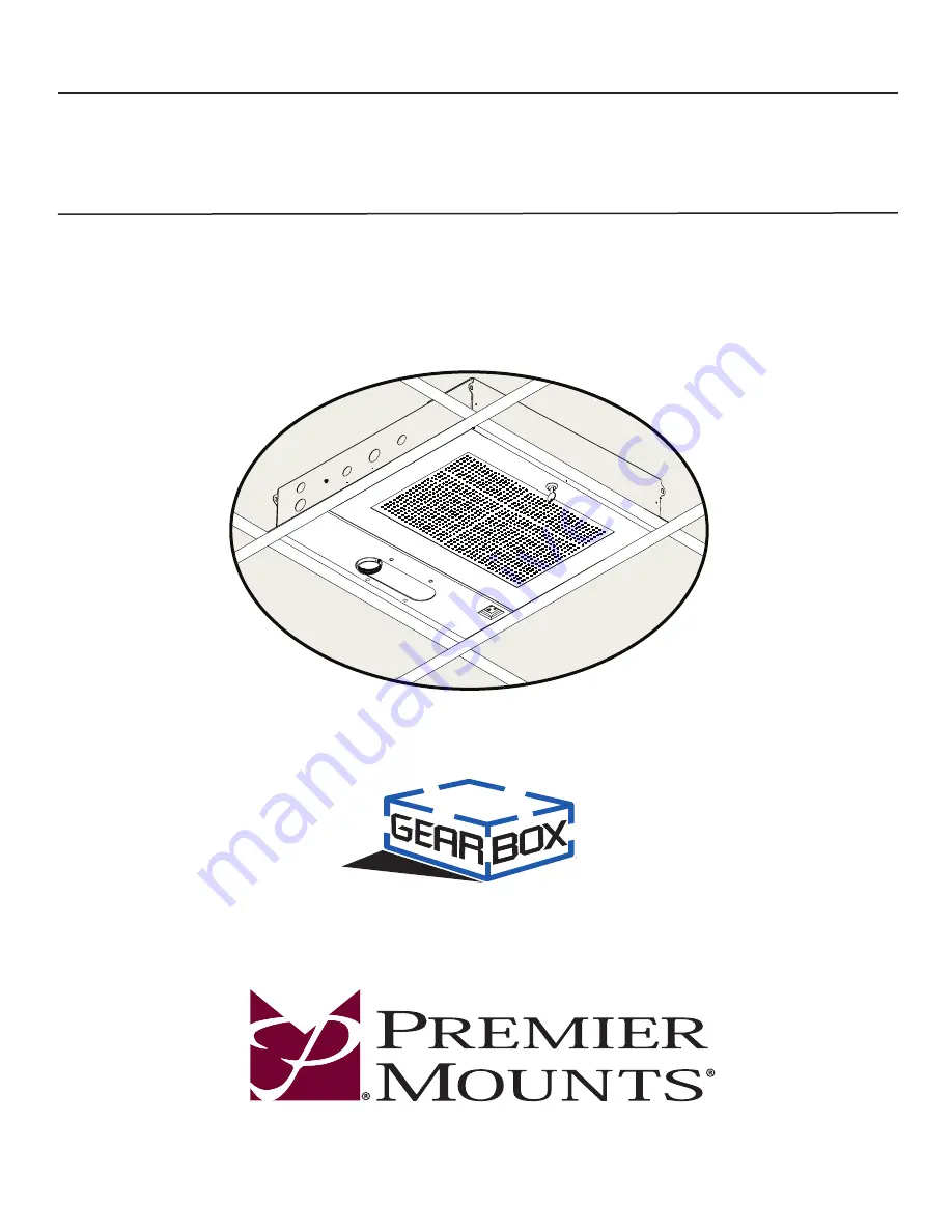
GB-AVSTOR5
Ceiling Equipment Storage Box with Pipe Coupler
9534-500-021-00
Page 1: ...INSTALLATION INSTRUCTIONS CREATING POSITIVE CUSTOMER EXPERIENCES GB AVSTOR5 Ceiling Equipment Storage Box with Pipe Coupler 9534 500 021 00...
Page 2: ...THE USE OF ANY PREMIER MOUNTS PRODUCT FOR PURPOSES OTHER THAN THOSE FOR WHICH IT WAS DESIGNED OR DAMAGE CAUSED BY UNAUTHORIZED ATTACHMENTS OR MODIFICATIONS AND IS NOT RESPONSIBLE FOR ANY DAMAGES CLAIM...
Page 3: ...tion If there are parts missing and or damaged stop the installation and call Premier Mounts at 800 368 9700 GB AVSTOR5 Ceiling Box Qty 1 GB AVSTOR5 Hardware M5 x 8mm Phillips Head Screws Qty 6 Pencil...
Page 4: ...ple 1 and 3 4 knockouts provide electrical conduit connector access The GB AVSTOR5 Ceiling Equipment Storage GearBox with integrated pipe coupler provides a secure and discrete storage and mounting so...
Page 5: ...e steps of this installation may require two people to prevent personal injury and or damage to your equipment Please observe all warnings in the following installation procedure and utilize proper sa...
Page 6: ...ed cables supplied Determine the mounting location Use a concrete drill bit to drill the mounting holes Place the concrete eye anchor bolts into the pre drilled holes and gently tap into place using a...
Page 7: ...uss Loop the braided cable around the truss Run the open end 1 16 braided cable through the loop Pull the open end down until the 1 16 braided cable tightens around the truss Repeat steps 1 3 for the...
Page 8: ...ble Mounting Hole Please follow the steps below in numerical order and to correctly install the Quick Lock Cable Kit To release or relieve tension on the 1 16 braided cable slide the release pin to di...
Page 9: ...ension pull the 1 16 braided cable through the other side of the Quick Lock Once the tension has been adjusted be sure that there is a minimum of 6 of excess 1 16 braided cable on the non weight beari...
Page 10: ...flow into the ceiling WARNING Do not install or modify electrical wiring unless you are a certified electrician Remove two 2 M4 x 8mm Phillips combo screws to detach the electrical box from the ceilin...
Page 11: ...electronic components onto the mounting tray Align the electronic components so that the weight is distributed as evenly as possible Run the zip ties through the mounting slots on the tray underneath...
Page 12: ...e 1 NPT Pipe to the GB AVSTOR5 below Ceiling NPT Adapter Plate Adjustment View of the ceiling NPT adapter plate inside the GB AVSTOR5 Secure the 1 NPT pipe to the mounting coupler and tighten the pipe...
Page 13: ...1 Re attach the ceiling box lid to the ceiling box Swing the ceiling box lid up into place Securing the Lid Step 2 Hold the lid in place Use a key supplied to lock the lid in place Do not release the...
Page 14: ...at www mounts com Installation Instructions Technical Specifications All measurements are in inches mm 6 000 152 40 23 875 606 43 21 500 546 10 5 05 128 21 21 500 546 10 22 390 568 71 5 000 127 23 875...
Page 15: ...discover a problem that you think may be covered by the warranty you MUST REPORT it in writing to the address below within thirty 30 days Proof of purchase an original sales receipt from the original...