Predator Gas SE Instruction Manual Download Page 25

25

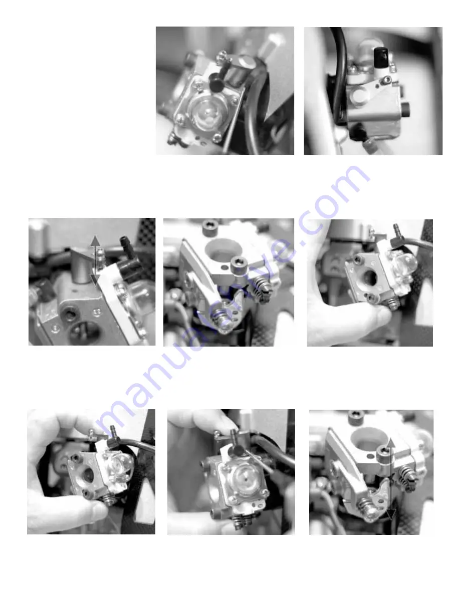
In the closed position it will be difficult 

to reach the set screw for the throttle arm. 

You  should  follow  these  guidelines  for 

optimal throttle performance in the Preda-

tor Gasser.

The  ball  for  the  throttle  lever  must  be 

placed in the furthest hole from the center 

for best deflection. 

Set the throttle to the full closed posi-

tion.The control ball on the throttle arm 

should be aligned as pictured aligned 

with the brass ball in the bulb plate.

This is the throttle control pointer plate. 

When the set screw is tightned, the throttle 

arm moves this plate.

Grab  the  throttle  pointer  and  move  it 

with your thumb until  exposing the set 

screw. Prepare your index finger to hold 

the position of the throttle arm.

After exposing the set screw carefully 

hold the position of the throttle pointer 

and  arm  in  order  to  tighten  the  set 

screw.

Try testing the method of positioning the 

arm. Tighten set screw with locktite only 

when position is final.

The halfway point on the throttle is found 

by aligning the flat long end of the throttle 

pointer with the bolt as shown.

Optimal Throttle Arm Positioning.

Following is a method of achieving 

maximum  deflection  range  in  the 

throttle  control. This  is  the  recom-

mended setup to get top performance 

out of your gas powered Predator.

Summary of Contents for Gas SE

Page 1: ...PAN 62 2 in 61 4 in TAIL ROTOR SPAN 10 5 in 11 2 in OVERALL LENGTH 56 9 in 56 9 in HEIGHT 18 in 18 in ENGINE Z231H Z260H Century Helicopter Products Designed and Developed in USA 4th Edition Copyright...

Page 2: ...is the responsibility of the owner to operate this product in a safe manner as it can inflict serious injury otherwise It is recommended that if you are in doubt of your abilities seek assistance from...

Page 3: ...Plug Hobby Scissors Double Sided Foam Tape 1 16 3 32 Foam Rubber radio packing JB Weld bond clutch lining Locktight 260 Green 242 Removeable 262 Permanent Hobby Grease Super Lube Oil to lubricate sli...

Page 4: ...ert one M3x6 button head screw through the right side hole of the offset plate see photo and thread into one tie bar Make two identical sub assemblies Note that the bear ing cups face outwards from th...

Page 5: ...earing and the thrust washer are properly seated into the deep end of the blade grip If necessary use a socket that matches the outside diameter of the bearing and press into position Make two assembl...

Page 6: ...lly grease is needed for thrust bearings and the tail rotor gears A light Lithium or Silicon grease should be used commonly found at hobbyshops for RC cars Step 8 Flybar Control Yoke PushrodAis alread...

Page 7: ...Again using the ruler rotate one paddle or the other to get equal distances remember leading edge of the paddles turn clockwise Set the length of pushrod B to 26mm center to center and attach to the b...

Page 8: ...ar frame HW6117B Landing Gear Frame M5x14 Coun tersunk Phillips Screws x 3 with engine HW6117B Landing Gear Frame M4x6 Socket Cap Screw x 2 M4x10 Socket Cap Screw x 2 M4x6x4 Spacer x 4 Step 13 Removea...

Page 9: ...e cooling fan shroud mount plate onto the face of the engine with the straight edge towards the cylinder head and the access hole on the muffler side Install four M5x8 socket cap screws to secure the...

Page 10: ...he fan shroud over the cooling fan and secure using three M2 5x8 socket cap screws using L242 Blue threadlock Tighten these until they stop and that s it do not torque these bolts If you plan to insta...

Page 11: ...eft side frame and the X frame Insert four M3x8 socket cap screws through the lower frames into the landing gear frame do not use threadlock at this time Press the spark plug cap over the spark plug i...

Page 12: ...ton head cap screws for fan shroud clearance from the vertical frame side and secure using two M3 locknuts locknuts need to be held with pliers from under the battery tray Step 23 Servo Front Lower Fr...

Page 13: ...Tank Spacer As you will notice the fuel tank will float between the front lower side frames Install the M3x10x17 fuel tank spacer on the right side frame into the center hole with one M3x8 socket cap...

Page 14: ...oth the upper and lower bearings inside the clutch shaft bearing block us ing alcohol Apply a small amount of L262 Red threadlock to the top edge of the clutch gear where it will contact the bearing P...

Page 15: ...torque rating Digital and analog servos will fly the Predator with ease as long as the minimum torque rating selected is 70oz in rated at 4 8 volts Install the four rubber gromments that are supplied...

Page 16: ...x 2 CNLR1020 Medium Ball x 4 CNBB37 M3x7 Ball Bear ing x 4 M3x30 Socket Cap Screw x 2 Stepped Spacer x 2 Step 36 Front CCPM Bellcranks Starting on the right side insert one M3x30 socket cap screw thro...

Page 17: ...HI6058H Machined Main Gear 88T CT Drive 1 2 3 4 1 2 3 4 1 2 3 4 1 2 3 4 Gas SE only HI6064A Autohub Inner Gear Sprague CT Drive HI6064B Autohub Outer Gear Sprague CT Drive HI6064D M15x18x0 20 Sprague...

Page 18: ...llar Inspect the bottom collar make sure that the reduced step diameter is towards the ball bearing Slide the bottom collar against the bearing and insert two M3x6 flat head cap screws using L242 Blue...

Page 19: ...lower larger ID Gas SE only HW6045B Thrust Bearing Spacer Step 45 Starting Shaft and Hex Coupler The gas kits include the regular starting shaft and hex coupler as in all the Predator kits to align t...

Page 20: ...17mm Rear Frame Spacers x 4 26mm Threaded Spacers x 2 26mm Threaded Hex Spacer 22mm Threaded Hex Spacer Step 47 Frame Spacers Ensure that the correct spacers are used in the correct locations when ass...

Page 21: ...chbell both fore aft and left right test by slowly pulling the starter cord Watch as the clutch turns to make sure that it does not turn the clutchbell at any point All the fasteners should be tighten...

Page 22: ...nt of Slo CA glue to the exposed threads and thread into the washout hub again being carefull not to overtighten the screw When correctly as sembled the screw is positioned on the left side see photo...

Page 23: ...al in speed and torque Install the rubber grommets and eyelets from the bottom of the servo tabs Install the two front CCPM servos from the outside of the servo side frames using eight M2 3x12 Phillip...

Page 24: ...arburetor Arm HW6192C Pushrod F 112mm center to center HW6192B Car buretor Arm M3x4 Set Screw Optional CN2288 Metal Servo Arm Pack 900 Degrees 900 Degrees CNLR1018 Ultra Short Steel Ball M2 Hex Nut CN...

Page 25: ...ttle arm moves this plate Grab the throttle pointer and move it with your thumb until exposing the set screw Prepare your index finger to hold the position of the throttle arm After exposing the set s...

Page 26: ...Pushrod B 26mm cen ter to center x 2 HW6001 M5x35 Socket Cap Screws x 2 M5 Locknut x 2 Main blade grips shown at 00 degrees When attaching all pushrods make sure that same length pushrods are actuall...

Page 27: ...nt landing struts to the skids HW6127C M3x15x19 Landing Gear Spacers x 4 M3x35 Socket Cap Screws x 4 M3x11 Flat Washers x 4 CNBB511 M5x11 Ball Bearing x 2 HW3057 Tail Bevel Gear HW6059 Tail Transmissi...

Page 28: ...he tail output shaft and position against the larger 14 teeth gear Then slide on the two M5x7 washers before sliding on the ball bear ing 5x13x4 Step 65 Tail Input Shaft Gear The tail output shaft has...

Page 29: ...ut x 3 Tail gear mesh is controlled by the gears Initially the tail mesh will be tight until the tail gears wear in M3x10 Socket Cap Screw M3x15 Socket Cap Screw mid top M3x20 Socket Cap Screw mid bot...

Page 30: ...thin race first larger inside diameter CNBB49T M4x9 Thrust Ball Bearing CNBB39 M3x9 Ball Bearing x 2 CNLR1003 M3x5x0 5 Micro Washer M3 Locknut x 2 HW3098A Steel Tail Ro tor Hub CNBB410 M4x10 Ball Bear...

Page 31: ...r x 2 Tail blade tension should be set tight enough that the rotor blade will stay straight on its own but will pivot easily when the blade tip is moved After flying the model if a vibration is notice...

Page 32: ...nd cap until it stops Allow it to cure overnight for highest strength HW6065 Tail Pushrod Set End Cap x 2 Carbon Tube CNLR1000S Tail Ball Link Grey x 2 M2 Pushrod Step 77 Rudder Servo Mount Insert the...

Page 33: ...boom and slide the matching fin mount with the tapered ends taller side of the taper toward the mechanics followed by the aluminum tail support struts and loosely install the two M3 locknuts Step 80...

Page 34: ...cable ties and trim the ends HI6082 Tail Support Bridge Half x 2 Cable Tie x 4 M3x15 Socket Cap Screw M3 Flat Washer x 2 M3 Locknut Gas SE only Step 83 Rudder Pushrod Completion Slide the two pushrod...

Page 35: ...5 socket cap screw through the rear holes and two M3x45 socket cap screws into the forward holes Slide one spacer onto each screws and finally slide the vertical fin mount half thinner than the horizo...

Page 36: ...After the gromments have been installed it is recommended to reinforce and bond them in place from the inside of the canopy Using Goop adhesive or Epoxy lift the inside edge and insert the adhesive b...

Page 37: ...Blocks HW6125A Wooden Blocks x 10 Blocks mounted flush to the canopy edge When attaching the canopy to the helicopter install the two M3x10 Phillips washer head screws to the upper canopy standoffs T...

Page 38: ...EW HW3057 TAIL TRANSMISSION BEVEL GEAR HW6059 TAIL TRANSMISSION DRIVE SHAFT Predator Gas Replacement Parts HW6062B TAIL BOOM 855mm GAS HW6063BS TAIL S S TORQUE DRIVE SHAFT GAS HW6065 TAIL PITCH CONTRO...

Reviews: