Precision matthews PM-30MV Manual Download Page 4

4

PM-30MV v3 2020-10

Copyright © 2020 Quality Machine Tools, LLC
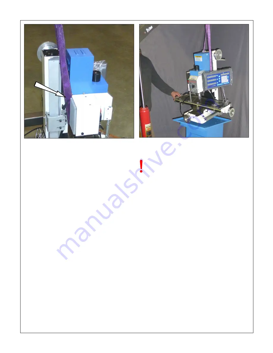
Figure 1-2  

Sling position

Figure 1-3  

Lowering the mill into position

Assembly and cleanup

Unfinished  metal  surfaces

 may be protected in shipping by 

thick grease and/or paper. Carefully remove these using a 

plastic paint scraper, disposable rags and a light-oil such as 

WD-40. Coat bright machined surfaces with a rust preventa-

tive such as Rustlick. 

Level the mill using the table surface for reference, shimming 

under the tray if necessary. Oil the ways and leadscrews (Z-ax-

is screw excepted, inaccessible).

Initial checks

Read Section 3 if unsure about any item in the following

1.  Check that: A There is no chuck or collet is installed; B 

There are no clamps or locks on moving parts, and; C The 

speed control knob is at its 

lowest setting

, fully count-

er-clockwise.

2.  Remove the blue motor cover. Make sure the belt is set 

for low speed (belt running on the larger spindle pulley.) 

If not, re-position the belt, Figure 3-2. Replace the motor 

cover. 

3.  Connect 220 Vac power.

4.  Be sure the E-Stop (Emergency) button has not been 

pushed  in  (it  should  pop  out  when  twisted  firmly  clock

-

wise). 

5.  Press the Power button. The power lamp and the tach 

display should light. 

6.  Check the emergency function by pressing the E-Stop 

button. The power lamp should go out, de-energizing the 

contactor circuit, disabling all electrics. 

If this doesn’t 

happen, the E-stop function is defective, and needs 

attention.

7.  Restore power by twisting the E-Stop button 

firmly

 to the 

right; this will cause it to pop out.

8.  Check that the chip guard switch disconnects power when 

the guard is swung out.

DO NOT LEAVE THE MACHINE UNATTENDED 

DURING THIS PROCEDURE

Test run procedure

1.  Select Forward (F) spindle direction. The tachometer 

should display between 50 and 100 rpm.

2.  Rotate the speed potentiometer cw for a speed of about 

200 rpm. Run the spindle at that speed for about 1 min-

ute, then progressively increase the speed to the max 

(about 1500 rpm), pausing for about 1 minute at each 

200 rpm increment.

3.  Repeat step (2) with the spindle reversed (R).

4.  Set the belt for high speed, then repeat steps (2) and (3).

The machine should now be ready for normal operations.

Summary of Contents for PM-30MV

Page 1: ...rive no gears Variable spindle speed from 50 to 3000 rpm Table size 33 x 8 1 4 Quill DRO for precise downfeed measurement Square column design heavy cast iron construction Options Table X axis power f...

Page 2: ...to install and use a mill As the owner of the mill you are solely responsi ble for its proper installation and safe use Consider the material contained in this manual to be advisory only Quality Mach...

Page 3: ...he machine from the pallet Install the largest of the four handles on the headstock handwheel top of column on right Install the three smaller handles on the X axis and Y axis handwheels 3 Release the...

Page 4: ...e motor cover 3 Connect 220 Vac power 4 Be sure the E Stop Emergency button has not been pushed in it should pop out when twisted firmly clock wise 5 Press the Power button The power lamp and the tach...

Page 5: ...l ing and fine milling downfeed options It is powered by a 2 HP 1 5 kW brushless dc motor Spindle speed is continuously variable from 50 to 1500 rpm low range and 1400 to 3000 rpm high range This is a...

Page 6: ...10V 60 Hz single phase Headstock Vertical travel 14 1 2 in Left right tilt 90 degrees clockwise counter clockwise Spindle Speed Low range 50 to 1500 rpm High range 1400 to 3000 Internal taper R8 Quill...

Page 7: ...e the work area is properly lit Never leave chuck keys wrenches or other loose tools on the machine Be sure the workpiece and machine ways are secure before commencing milling or drilling hold downs a...

Page 8: ...not run if the chip guard is open The spindle motor is controlled by a three position switch Forward F Stop O Reverse R and a continuously vari able speed control knob F Forward clockwise looking dow...

Page 9: ...le support ing the R 8 device with the other hand R8 tooling is located in the spindle bore by a set screw If it is difficult or impossible to insert the R8 device chances are the set screw is in too...

Page 10: ...an inch scale on the column For more precise positioning the crank hub has a graduated dial with 0 001 divisions be aware of backlash in the bev el gears controlling the Z axis leadscrew and also in...

Page 11: ...put without locking For edge finding and table positioning with or without DROs be wary of the quill lock Figure 3 11 Workpiece positioning example 1 Install an edge finder in collet or chuck a tip di...

Page 12: ...tock to be rotated The headstock is top heavy and may swing suddenly to either side unless a helper is on hand to restrain it Testing for moveability as you go carefully loosen the nuts by degrees Be...

Page 13: ...ale 8 Note the dial indicator and DRO readings then back off the fine downfeed at least a couple of turns to avoid colli sion when sweeping 9 Reposition the 1 2 3 block to the opposite location on the...

Page 14: ...k is tilted again 2 Shimming between the underside of the column and the main base casting This is a long term fix It is a two per son procedure requiring an engine hoist or some other means of un wei...

Page 15: ...ball Oil pressure will dis place the ball allowing oil to flow provided the oil can tip is firmly pressed onto the brass seating Before oiling check that the ball is not stuck press it lightly with a...

Page 16: ...d in a similar position on the other side of the leadscrew Figure 4 4 Y axis backlash adjustment A second screw is located in a similar position on the other side of the leadscrew DOWNFEED RETURN SPRI...

Page 17: ...uill assembly 8 Lock the quill Figure 3 8 then raise the headstock careful ly Slowly release the quill locking lever while supporting the quill assembly from below There is nothing to stop the unlocke...

Page 18: ...manual feeding right hand handwheel to check for proper engagement of the gears Gear engagement Proper engagement is hard to specify The separation that should exist between the gears can be gaged in...

Page 19: ...19 PM 30MV v3 2020 10 Copyright 2020 Quality Machine Tools LLC Section 5 PARTS Model PM 30MV ELECTRICAL SCHEMATIC Fig 1...

Page 20: ...Front panel Z5373 4 Screw M4 8 Z5374 6 Potentiometer Z5375 7 Direction switch Z5376 8 Power ON OFF Z5377 9 Fuse 5 A Z5378 10 Washer 4 Z5379 11 Tach display Z5380 12 Contactor rail Z5381 13 Contactor Z...

Page 21: ...21 PM 30MV v3 2020 10 Copyright 2020 Quality Machine Tools LLC PM 30MV HEADSTOCK Fig 4 Speed sensor and bracket 41 Optically detects holes in index ring 82...

Page 22: ...Leaf spring Z5434 46 Screw M3 6 Z5435 47 Speed sensor bracket Z5436 48 Screw M3 Z5437 49 Lock handle M8 25 Z5438 50 Screw M10x10 Z5439 51 Belt PJ457 6 Z5440 52 Pulley Z5441 53 Screw M6 16 8 Z5442 54 M...

Page 23: ...6 Z5507 Ref Description Part 17 Pipe connector Z5508 18 Table Z5509 19 Dovetail nut Z5510 20 Spacer Z5511 21 Screw M6 10 Z5512 22 Rivet 2 5 Z5513 23 Scale Z5514 24 Base Z5515 25 Gib screw Z5516 26 Sad...

Page 24: ...COLUMN Fig 6 Dimensions in millimeters Ref Description Part 23 Cover plate Z5560 24 Screw M8 25 Z5561 25 Screw M5 8 Z5562 26 Cap Z5563 27 Nut M16 1 5 Z5564 28 Bearing 51203 Z5565 29 Copper sleeve Z556...

Reviews: