


16
PM-30MV v3 2020-10
Copyright © 2020 Quality Machine Tools, LLC
LEADSCREW BACKLASH CORRECTION
When alternating between clockwise and counter clockwise ro-
tation of the X or Y leadscrews, the handwheel moves freely a
few degrees but the table stays put. This is backlash, a feature
of all leadscrews other than the precision type found on CNC
machines. The acceptable amount of lost motion depends on
the user, but 0.005” is generally a good compromise. Smaller
numbers are possible, but overdoing it can lead to premature
wear of leadscrew and nut.
Excessive backlash can be corrected by compressing the
leadscrew split nut. For the X-axis this is done by tightening
the socket head screws on each side of the leadscrew, Figure
4-3. A long-handled 4 mm hex key is required, ideally one with
an extra-thick shank to minimize flexing.
The Y-axis leadscrew nut has two similar adjusting screws,
normally concealed by the solid rubber way cover at the back
the table, Figure 4-4. A universal-jointed driver, or other type of
flexible driver, is necessary to adjust the screws.
Figure 4-3
X-axis backlash adjustment
A second screw is located in a similar position on the other side of
the leadscrew.
Figure 4-4
Y-axis backlash adjustment
A second screw is located in a similar position on the other side of
the leadscrew.
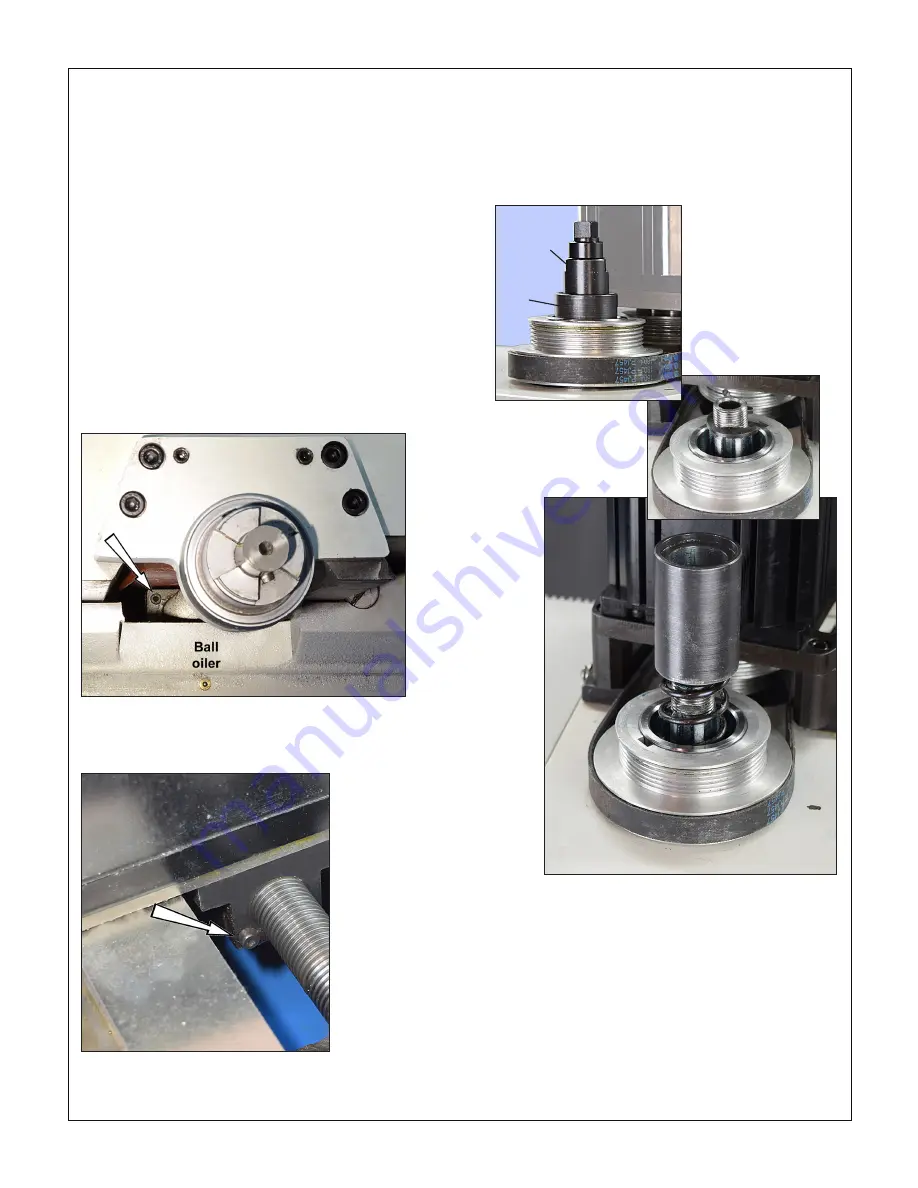
DOWNFEED RETURN SPRING
The quill should automatically retract when the coarse down-
feed levers are released following a drilling operation. If it does
not, check the quill locking lever. The quill return spring, Figure
4-5, is contained in a spring cup which is locked to the spin-
dle by a special retaining clip beneath the spindle cap. Spring
force is not adjustable.
SPINDLE BEARINGS
The spindle runs on grease-lubricated tapered roller bearings.
These should be serviced every 500 hours of running time.
Thoroughly clean each bearing assembly then repack with
a grease such as Kluber Isoflex (auto shop wheel bearing
grease can be used in low-load, low rpm operations).
Do not over-pack the roller bearings!
Bearing manufacturers recommend that the free volume be-
tween inner and outer should be no more than 30% filled with
Figure 4-5
Quill return spring
Spindle top assembly. The
internally-threaded top cap
screws onto the spindle,
securing the retaining clip
(below), which in turn holds
the spring cup in place.
Spindle
top cap
Return
spring
cup
The retaining clip locates
in grooves on each side
of the spindle (spring cup
removed for this photo)