27
PM-1228VF v3 2021-05
Copyright © 2021 Quality Machine Tools, LLC
INSTALLING DRO SCALES
Because no two owner-installed DRO installations are iden-
tical — even on similar machines — the following notes are
mostly suggestions, not detailed instructions.
Installing a DRO scale on the longitudinal axis, in line with the
lathe bed, is usually straightforward.
Not so for the cross-
slide scale:
there are several choices here depending on user
preferences — for instance, whether or not the installation has
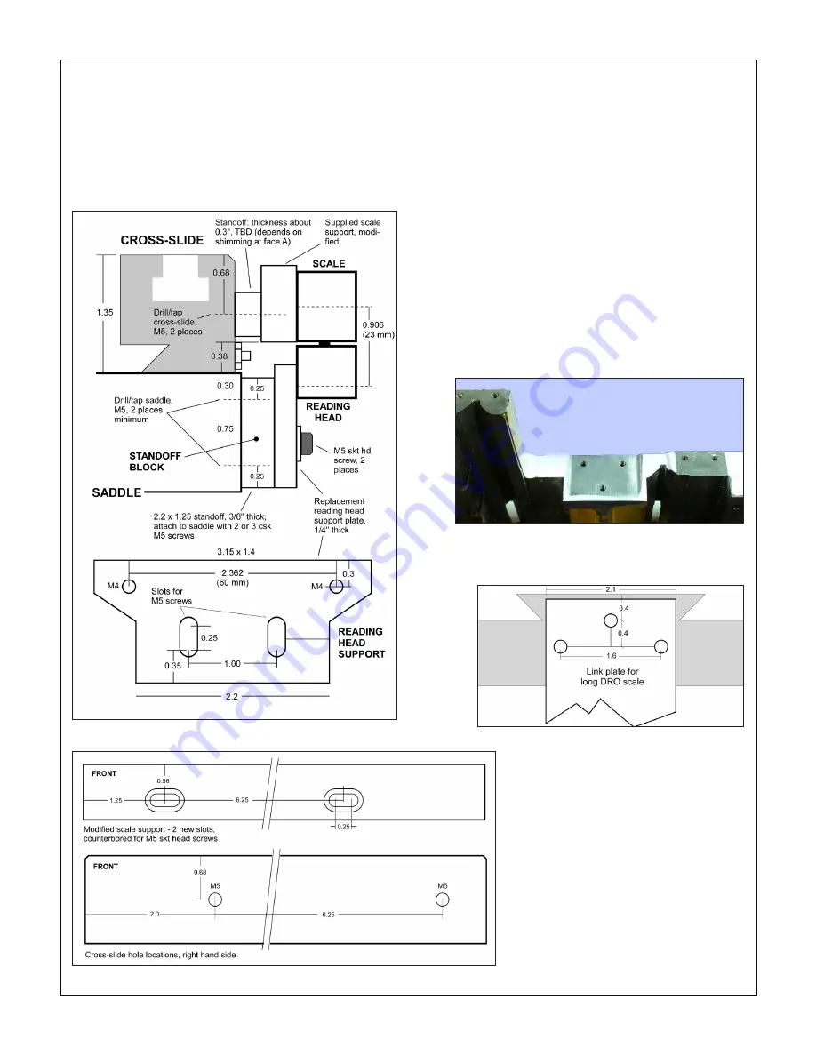
Figure A
Suggested attachment of DRO scale to cross-slide
Figure B
Modified scale support & cross-slide holes
Figure C
Surface for standoff block, RH side of saddle
This surface was milled to be truly vertical, in line with the cross-slide
dovetails. No mill? Set screws in the standoff block (or shims) can be
used instead to correct alignment. Drill & tap 2 or 3 holes.
Figure D
Back surface of the saddle
Drill & tap 2 or 3 M5 (or 10-32) holes. Like the
right hand surface, Figure C, this can be done
with a drill press or mill if the saddle is removed
to allow access to the saddle and cross-slide lock screws, and/
or to the cross-slide gib screws. The follower rest is another
instance. If this is likely to be needed in upcoming projects,
the cross-slide DRO scale has to be installed on the right-hand
side of the cross-slide.
In the following example installation, the scale is on the right
side, and it does allow access to: 1. Cross-slide lock screw; 2.
Saddle lock screw, and; 3. Cross-slide gib screws. It does not
interfere with the follower rest.
Keep in mind that this is a
suggested installation
, with draw-
ings intended only as a starting point Before cutting metal,
compare the drawings and photos with your machine. Dimen-
sions can change without notice. Also, surfaces that were ma-
chined on the sample may be raw or hand finished on other
models. Expect to do a lot of planning, and precise shop work.
Doing this right takes care and attention!
All glass scale DROs are similar in principle, but differ widely
in practice. These notes describe the 2-axis kit supplied by
Precision Matthews. The kit comes with two
support plates, one for the reading head, the
other for the scale. Expect to do a few hours
of shop work — example, a shop-made
sup-
port plate
, Figure A, for the reading head
was used in place of the supplied plate. Be-
tween the support plate and the saddle is a
shop-made
standoff block
.
A milling machine is helpful but not essen-
tial. If available, a mill can be used to square
and flatten mounting surfaces, and also to
machine counterbored slots for easier instal-
lation.


