10
•
Installation
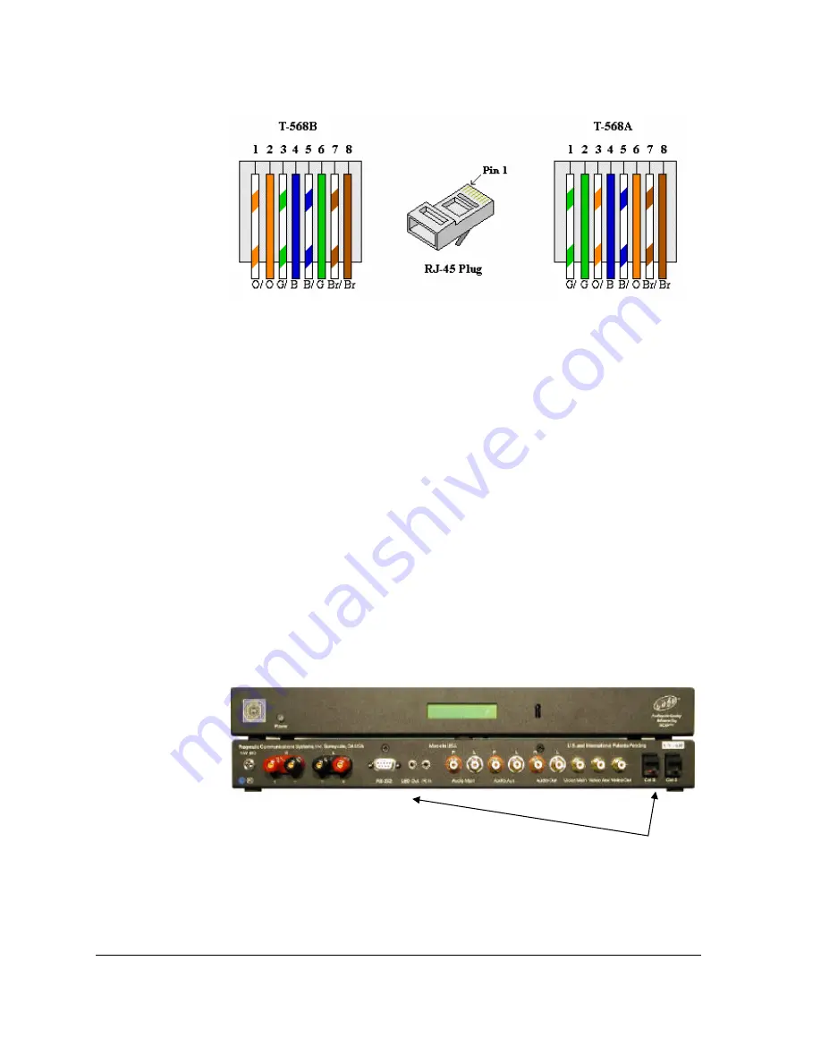
Figure 1: Wiring plans
We recommend using plan T-568B.
Before connecting units we recommend to test the integrity of the cables and the connectors
using a cable analyzer (such as AtlasIT). Loose or broken wires may stop the network
functioning.
Step 2—connecting the CATS™ units
To ensure normal operation the CATS™ units must be connected to CAT5 cables according to
the house wiring diagram. Please refer to the CATS™ User’s Manual for more information.
1. CATS™ RJ-45 pin-out
The following wires are used in CATS™ network:
•
1, 2 – RS485 (A) and RS485 (B) NOTE: USE DB-9 pins 2 & 3 for new designs
•
3, 4, 5, 6 – Audio/Video and infrared IR traffic
•
7, 8 – grounded.
The new generation of CATS™ units (firmware 2.3) does not use RJ45 pins for RS485
signaling. The DB9 socket is used instead. Please check the integrity of the RS485 network
before using it.
Figure 2: CATS™ connectors
Split CAT5 cable for the new
generation of units as follows:
•
RJ45 pin 1 – DB9 pin 2
•
RJ45 pin 2 – DB9 pin 3
Summary of Contents for CATS-KP
Page 4: ......
Page 8: ......
Page 12: ......
Page 18: ......
Page 30: ......
Page 32: ......
Page 34: ......
Page 35: ...Appendix I Network example 35 CATS KP Appendix I Network example...
Page 36: ......
Page 37: ...Notes 37 CATS KP Notes...


