background image

5104V104-UK

 5

Ec DEcLARATION Of cONfORmITY

As manufacturer

PR electronics A/S 
Lerbakken 10 
Dk-8410 Rønde

hereby declares that the following product:

Type: 5104 
Name: Repeater / Power Supply

is in conformity with the following directives and standards:

The EMC Directive 2004/108/EC and later amendments

EN 61326-1 : 2006

  For specification of the acceptable EMC performance level, refer to the 

electrical specifications for the device.

The Low Voltage Directive 2006/95/EC and later amendments

EN 61010-1 : 2001

The ATEX Directive 94/9/EC and later amendments

EN 50014 : 1997 E incl. A1+A2, EN 50020 : 2002 E 
and EN 50281-1-1 : 1998 incl. A1 
ATEX certificate: DEmkO 99ATEX126013

No changes are required to enable compliance with the replacement standards: 

EN 60079-0 : 2009 and EN 60079-11 : 2012

Notified body:

UL International Demko A/S 
Lyskaer 8, P.O. box 514
2730 Herlev
Denmark 

Rønde, 5 November 2012 

Kim Rasmussen 


Manufacturer’s signature

Summary of Contents for PRetrans 5104

Page 1: ...S I G N A L S T H E B E S T 5 1 0 4 R e p e a t e r P o w e r S u p p l y N o 5 1 0 4 V 1 0 4 U K F r o m s e r n o 0 3 0 2 5 0 0 0 1 ...

Page 2: ... electronics A S offre une large gamme de produits pour le traite ment des signaux analogiques et numériques dans tous les domaines industriels La gamme de produits s étend des transmetteurs de température aux afficheurs des isolateurs aux interfaces SI jusqu aux modules universels Vous pouvez compter sur nos produits même dans les conditions d utilisation sévères p ex bruit électrique vibrations ...

Page 3: ...ion 3 Safety instructions 3 EC declaration of conformity 5 How to demount System 5000 6 Application 7 Technical characteristics 7 Mounting installation 7 Applications 8 Order 5104 9 Electrical specifications 9 DIP switch programming 12 Connections 13 Block diagram 14 UL Control Drawing 5104QU01 15 ...

Page 4: ...s voltages can occur and it must only be connected to the programming unit Loop Link by way of the enclosed cable GENERAL INSTAL LATION HAZARD OUS VOLTAGE Warning This device is designed for connection to hazardous electric voltages Ignoring this warning can result in severe personal injury or mechanical damage To avoid the risk of electric shock and fire the safety instructions of this manual mus...

Page 5: ...or trained to mount operate and also troubleshoot technically correct and in accordance with safety regulations Operators being familiar with the contents of this manual adjust and operate the knobs or potentiometers during normal operation Receipt and unpacking Unpack the module without damaging it The packing should always follow the module until this has been permanently mounted Check at the re...

Page 6: ...the device The power switch should be marked with a label telling it will switch off the voltage to the device Year of manufacture can be taken from the first two digits in the serial number Calibration and Adjustment During calibration and adjustment the measuring and connection of external voltages must be carried out according to the specifications of this manual The technician must use tools a...

Page 7: ...rformance level refer to the electrical specifications for the device The Low Voltage Directive 2006 95 EC and later amendments EN 61010 1 2001 The ATEX Directive 94 9 EC and later amendments EN 50014 1997 E incl A1 A2 EN 50020 2002 E and EN 50281 1 1 1998 incl A1 ATEX certificate DEMKO 99ATEX126013 No changes are required to enable compliance with the replacement standards EN 60079 0 2009 and EN ...

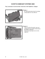
Page 8: ...unt the connectors with hazardous voltages Picture 1 By lifting the bottom lock the device is detached from the DIN rail Picture 2 Then by lifting the upper lock and pulling the front plate simultaneously the PCB is removed Switches and jumpers can now be adjusted ...

Page 9: ...t ranges in the 5104 can be selected by the internal DIP switches without the need for a recalibration Special measurement ranges can be delivered PR5104 is based on microprocessor technology for gain and offset The analogue signal is transmitted at a response time of less than 25 ms Inputs outputs and supply are floating and galvanically separated The output can be connected either as an active c...

Page 10: ...8 5104V104 UK Applications 3 wire transmitter Current mA Voltage 2 wire transmitter Output Supply Supply Supply Supply Output Output Output ...

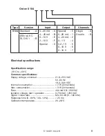
Page 11: ... 3 W 2 channels Fuse 400 mA SB 250 VAC Isolation voltage test operation 3 75 kVAC 250 VAC Signal noise ratio Min 60 dB 0 100 kHz Response time 0 90 100 10 25 ms Calibration temperature 20 28 C Order 5104 Type Version Input Output Channels 5104 Standard A 0 20 mA A 4 20 mA B 0 10 V E 2 10 V F Special X Special 0 0 20 mA 1 4 20 mA 2 0 1 V 4 0 2 1 V 5 0 10 V 6 2 10 V 7 Single A Double B EEx ia II C I...

Page 12: ... range span 16 mA Max offset 20 of max value Input resistance nom 10 Ω PTC 10 Ω Voltage input Measurement range 0 10 VDC Min measurement range span 8 VDC Max offset 20 of max value Input resistance 2 MΩ Current output and 2 wire 4 20 mA output Signal range span 0 20 mA Min signal range span 16 mA General values Input type Absolute accuracy Temperature coefficient All 0 1 of span 0 01 of span C Bas...

Page 13: ...icable for zone 0 1 2 20 21 or 22 UL IS Cl I Div 1 Group A B C D IS Cl I zone 0 og 1 Group IIC IS Cl II Div 1 Group E F G UL Control Drawing No 5104QU01 Ex I S data Um 250 V Uo 28 VDC Io 93 0 mADC Po 0 65 W Lo 3 mH Co 0 08 µF Marine approval Det Norske Veritas Ships Offshore Standard for Certification No 2 4 GOST R approval VNIIM VNIIFTRI Cert No See www prelectronics com Observed authority requir...

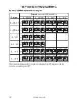
Page 14: ... 1 2 2 3 4 1 1 2 2 3 4 1 1 2 2 3 4 1 1 2 2 3 4 1 1 2 2 3 4 1 1 2 2 3 4 1 1 2 2 3 4 1 1 2 2 3 4 1 1 2 2 3 4 1 1 2 2 3 4 1 1 2 2 3 4 DP 1 DP 2 DP 1 DP 2 DP 1 DP 2 DP 1 DP 2 DP 1 DP 2 DP 1 DP 2 DP 1 DP 2 DP 1 DP 2 DP 1 DP 2 DP 1 DP 2 DP 1 DP 2 DP 1 DP 2 DP 1 DP 2 DP 1 DP 2 DP 1 DP 2 DP 1 DP 2 DP 1 DP 2 DP 1 DP 2 DP 1 DP 2 DP 1 DP 2 On Off On Off On Off On Off On Off On Off Output Input channel 2 DP 3...

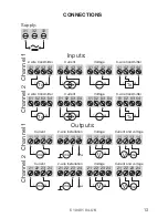
Page 15: ...52 54 53 41 42 44 43 Tx 51 52 54 53 Tx 41 42 44 43 41 42 44 43 41 42 44 43 Tx Tx 51 52 54 53 Supply Outputs Current Current Voltage Voltage Current and voltage Current and voltage 2 wire installation 2 wire installation Channel 1 Channel 2 Channel 2 2 wire transmitter Current Voltage Inputs Channel 1 2 wire transmitter Current Voltage 3 wire transmitter 3 wire transmitter ...

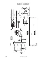
Page 16: ...DP4 DP1 DP3 CH 1 CH 2 1 2 3 4 1 2 T x V 33 44 43 42 41 54 53 52 51 31 14 13 12 11 24 23 22 21 1 0 Ω 2 M Ω V r e g P T C Supply Supply I Output V Output I V Output Channel 1 Channel 2 Ex barrier only 5104B Gnd Loop supply Input gnd Input V Input I 2 wire installation 24 230 VAC 24 250 VDC ...

Page 17: ...not be interconnected in any way 4 Install in Pollution degree 2 or better 5 Use 60 75 C copper conductors with wire size AWG 26 14 6 Warning Substitution of components may impair intrinsic safety 5104B Associated apparatus parameters CH1 Terminals 41 to 44 CH2 Terminals 51 to 54 Vt Uo 28 V It Io 93 mA Po 0 65 W IIC grp A B IIB grp C IIA grp D Ca Co 0 052 μF 0 44 μF 1 45 μF La Lo 2 4 mH 12 mH 20 m...

Page 18: ... Galvanic isolators for analogue and digital signals as well as HART signals A wide product range with both loop powered and universal isolators featuring linearisation inversion and scaling of output signals Isolation Interfaces for analogue and digital signals aswellasHART signalsbetweensensors I Pconverters frequency signals and control systems in Ex zone 0 1 2 and for some modules in zone 20 2...

Page 19: ...sales prelectronics it www prelectronics se sales prelectronics se www prelectronics co uk sales prelectronics co uk www prelectronics com sales prelectronics com www prelectronics cn sales prelectronics cn Head office Denmark www prelectronics com PR electronics A S sales prelectronics dk Lerbakken 10 tel 45 86 37 26 77 DK 8410 Rønde fax 45 86 37 30 85 ...

Reviews: