background image

4/12 


INSTALL THE LIGHTING FIXTURE 


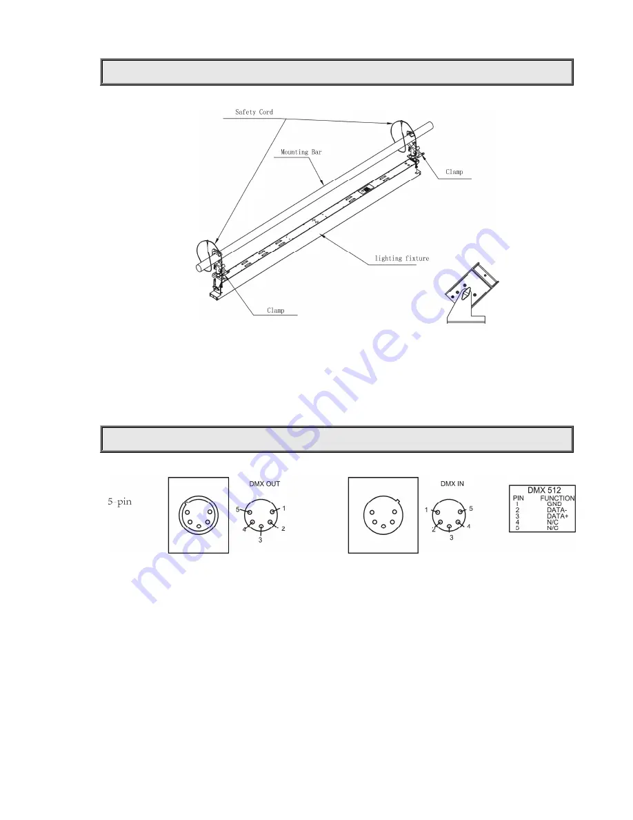
When the lighting fixture is used, as the right figure above, unfold the support to certain angle and put the lighting fixture onto a 

flat surface. Make sure it is steady. 

 
When the lighting fixture is used at a high place, as the left figure above, fold the support, turn it round to the top of the lighting 

fixture,  connect  a  lamp  hook  to  the  mounting  hole  reserved  in  the  support  by  screws,  and  then  hang  the  hook  to  a  high  place. 
Eventually, use the safety cord provided to pass through the handles and hang it as a second safety fixing. 


CONTROL SYSTEM AND POWER CONNECTION 


Connection  between  the  controller  and  a  lighting  fixture  and  between  one  lighting  fixture  and  another  must  be  made  with  a  2 
core-screened cable, with each core having at least a 0.5mm diameter. Please use the lighting fixture’s cannon 5- pin signal input and 
output cables as connection. The 5-pin signal connections are connected as shown in the figure above.   
Note: Care should be taken to ensure that none of the pins touch the metallic body of the plug or each other. The body of the plug is not 
connected in any way. The device accepts digital control signals in protocol DMX512 (1990).   
 
 
As for power connections, each lighting fixture has to be supplied separately by external power. Use the power cord of each lighting 
fixture to connect the mains power directly, making sure the voltage and frequency marked on the panel of the lighting fixture match 
what is supplied.


Summary of Contents for LED Studio 3500D

Page 1: ... product manual contains important information about the safe installation and use of this lighting fixture Please read and follow these instructions carefully and keep this manual in a safe place for future reference PR LIGHTING LTD http www pr lighting com ...

Page 2: ...ual we reserve the right to change specifications in the course of product improvement The publishers cannot be held responsible for the accuracy of the information herein or any consequence arising from them Every unit is tested completely and packed properly by the manufacturer Please make sure the packing and or the unit are in good condition before installation and use Should there be any dama...

Page 3: ...ighting fixture can be only used indoors IP20 The lighting fixture is not designed or intended to be mounted directly on to inflammable surfaces lighting fixture is only intended for installation operation and maintenance by qualified personnel Do not project the beam onto inflammable surfaces minimum distance is 2m 2m Avoid direct exposure to the light from the lamp The light is harmful to eyes D...

Page 4: ...ller and a lighting fixture and between one lighting fixture and another must be made with a 2 core screened cable with each core having at least a 0 5mm diameter Please use the lighting fixture s cannon 5 pin signal input and output cables as connection The 5 pin signal connections are connected as shown in the figure above Note Care should be taken to ensure that none ofthe pins touch the metall...

Page 5: ...connected with a DMX terminator This prevents electrical noise from disturbing and corrupting the DMX control signals The DMX terminator is simply an XLR connector with a 120Ω ohm resistor connected across pins 2 and 3 which is then plugged into the output socket on the last lighting fixture in the chain The connections are illustrated below ...

Page 6: ...herwise off TO SET THE DMX STARTADDRESS Each device must be given a DMX start address so that the correct lighting fixture responds to the correct control signals This DMX start address is the channel number from which the lighting fixture starts to listen to the digital control information being sent out from the controller The device has Two Channel Modes 1 Channel Mode has 1 channel so set the ...

Page 7: ...ng 4 Channel Mode Channel FUNCTION DMX DESCRIPTION 1 The first part Dimmer 000 255 Dimming 2 The second part Dimmer 000 255 Dimming 3 The third part Dimmer 000 255 Dimming 4 The forth part Dimmer 000 255 Dimming INDICATION OF LED CHARACTER DMX Indication On DMX signal OK Off No DMX signal ...

Page 8: ... g alcohol to clean housing of the apparatus TROUBLESHOOTING PROBLEM ACTION The lighting fixture doesn t switch on Power connection is not correct Power supply is damaged or abnormal Call a qualified personnel to fix it Connection of control board is not correct Call a qualified personnel to fix it The lighting fixture can be turned on but LEDs do not emit light and are out ofcontrol Connection of...

Page 9: ...Hours DIMMER 0 100 linearly adjustable COLORTEMPERATURE PR 3500T 3200K PR 3500D 5600K CRI Ra 86 Luminous Flux 5000 lm LIGHTANGLE FieldAngle 1 10 Maximum θ 0 80 CONTROL DMX512 5 pin interfaces Two Channel Modes 1 CH 1 Channel 4CH 4 Channels HOUSING Extruding aluminum IP20 WORK ENVIRONMENTTEMPERATURE 20 C 40 C WEIGHT Net weight 4 2kg Gross weight 6 8 kg ...

Page 10: ...10 12 SIZES 300 20 300 20 185 8 0 1 8 0 0 Electrical Diagram ...

Page 11: ...12 COMPONENT ORDER CODES NAME PARTNO QUANTITY REMARK Power Switch 192010134 1 10W LEDWhite 150020255 12 CT3200Kfor PR 3500T 10W LEDWhite 150020252 12 CT5500Kfor PR 3500D PR 3500 Control Board W 230060309 1 ...

Page 12: ...12 12 PR LIGHTING LTD PR New Hi tech Science Park 1582 XingyeAvenue Nancun Panyu Guangzhou 511442 China TEL 86 20 3995 2888 FAX 86 20 3995 2330 P N 320020125A Version 20140711 ...

Reviews: