


8
1 . Disconnect and lockout power before starting wiring procedure .
The CSR Smart Roll is provided with a ½ inch 90° elbow conduit access port and a strain relief . The Smart Roll cable is 2 wire, 22
AWG, PVC jacket, PVC insulation, and 6 feet in length . No set-up is required to the sensor inside the Smart Roll . It is factory set and
maintenance free .
DO NOT apply voltage directly across the wires of the Smart Roll Sensor, permanent damage may result . The Smart Roll is designed to
be used with a Smart Monitor, PLC, or similar device .
DO NOT use an incandescent light bulb as a load . An overload will occur due to extremely high cold current .
DO NOT operate without a load . A dead short will result which may cause irreparable damage .
DO NOT directly operate a motor with the sensor . Always use a relay or other appropriate device .
2 . At this point a 2 wire cable needs to be routed from the control box housing the Smart Monitor to the Smart Roll . It is recommended to
use minimum of 22 AWG shielded cable . Shielded cable eliminates electromagnetic interference (EMI) .
It is advisable to route the wires/
conduit for the Smart Roll away from electrical power conduit as the electrical power may cause electromagnetic interference (EMI) in the
signal from the Smart Roll. If EMI is present the signal from the Smart Roll may not make it to the Smart Monitor or PLC. This will result in
the Smart Monitor or PLC getting faulty readings.
Conduit from the control box to the Smart Roll offers more protection to the cable . Any nick, gouge, or cut in the cable wiring could
prevent the sensor signal from reaching the Smart Monitor .
If flexible conduit is used then the strain relief is not needed and can be removed . PPI recommends the wires or flexible conduit be
routed along the side of the CSR bracket and towards the hinge point . This will allow for free motion of the hinge . Be sure the wires or
conduit will not hinder the pivoting of the smart roll .
PPI is not capable of being aware of all site and industry electrical requirements for an application, and cannot be held liable for
non-compliant installations. The product has been designed to be capable of meeting many requirements, and a qualified individual should
review the connection plan prior to installation. Connection of conduit to 90° elbow conduit access port does not meet intrinsically safe
requirements.
DO NOT PULL THE WIRES CONNECTED TO THE SMART ROLL. Pulling wire from inside the roll will cause damage and void warranty. Be
sure to protect the wire near elbow threads and all corners, as this may damage the wire/insulation.
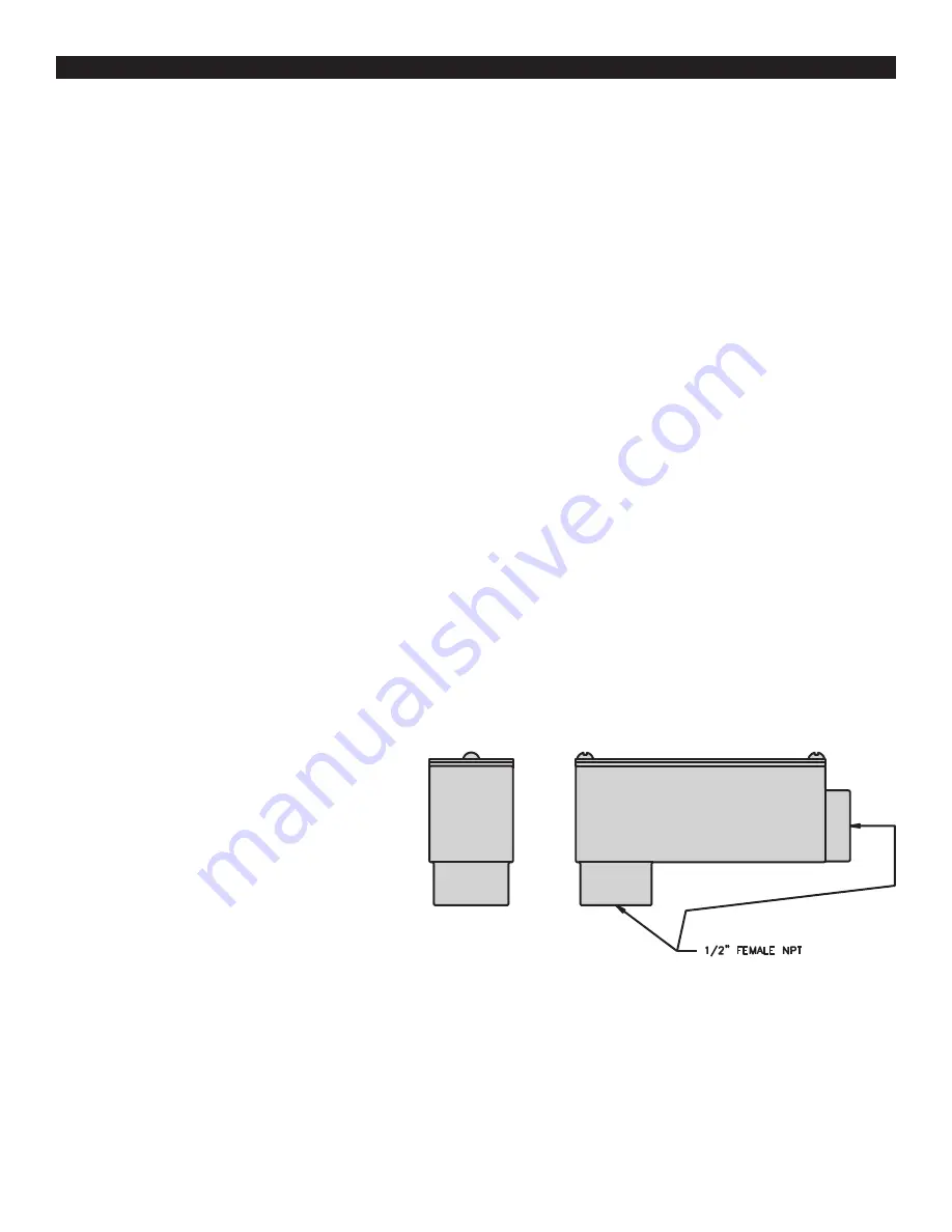
3 . Remove the cover from the 90° elbow conduit access
port and route the Smart Roll wires and the wires from
the control box through the conduit opening in the 90°
elbow access port and out the rectangular opening .
4 . Attach the conduit to the 90° elbow access port .
5 . Attach the Smart Roll wires to the wires from the control
box . Cut wires to proper length to fit in junction box . DO
NOT apply power to the sensor at this time . The Smart
Monitor or PLC provides the power for the Smart Roll .
To avoid damage, verify the circuit meets the sensor
specifications shown in Section A4 prior to applying
power .
6 . Reinstall junction box lid and tighten screws to secure .
FIGURE 3 .1: 90° Elbow Conduit Access Port .
WIRING THE SMART ROLL


