


20
sure to protect the wire near elbow threads and all corners,
as this may damage the wire/insulation.
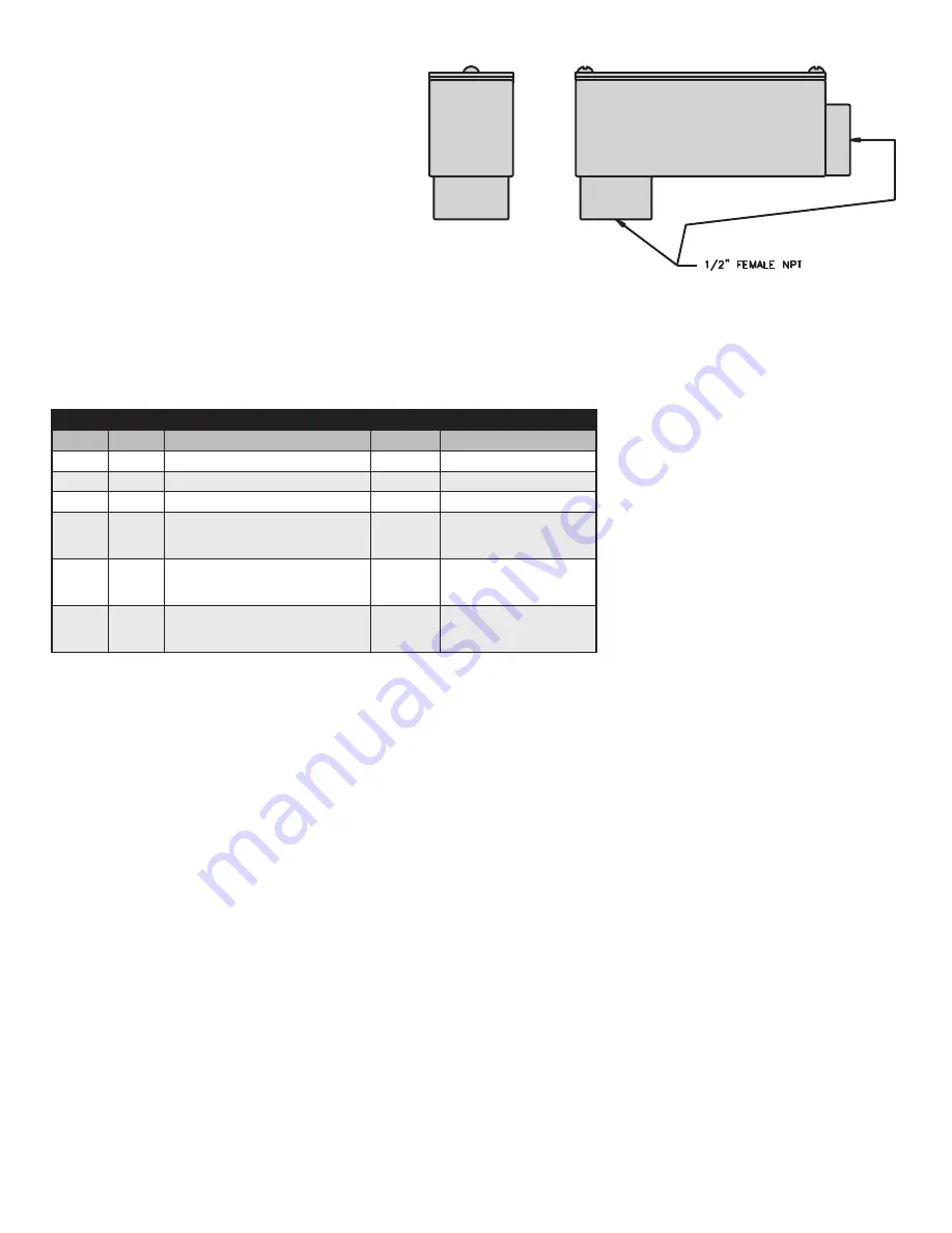
3 . Remove the cover from the 90° elbow conduit access
port and route the Smart Roll wires and the wires from
the control box through the conduit opening in the 90°
elbow access port and out the rectangular opening .
4 . Attach the conduit to the 90° elbow access port .
5 . Attach the Smart Roll wires to the wires from the control
box . Cut wires to proper length to fit in junction box . DO
NOT apply power to the sensor at this time . The Smart
Monitor or PLC provides the power for the Smart Roll .
To avoid damage, verify the circuit meets the sensor
specifications shown in section A4 prior to applying
power:
6 . Reinstall junction box lid and tighten screws to secure .
7 . Proceed to Section 4: “Wiring the Smart Monitor” .
FIGURE 3 .1: 90° Elbow Conduit Access Port .
ASSEMBLY COMPONENTS
ITEM
QTY
DESCRIPTION
PART #
1
1
Smart Roll
TABLE
2
1
Hex Bushing
34461
Provided with Smart Roll
3
1
90º Elbow Conduit Access Port
34452
Provided with Smart Roll
4
1
20º Center Clip
35º Center Clip
45º Center Clip
00820
00835
00845
Not provided with Smart Roll .
Use existing Center Clip or
order required part number .
5
1
B End Clip
31800
Not provided with Smart Roll .
Use existing End Clip or order
part number 31800 .
6
1
#12–3/8” Screw
31880
Not provided with Smart Roll .
Use existing Screw or order
part number 31880 .


