


56
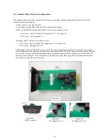
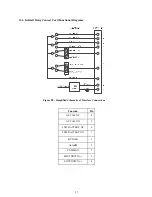
11.3 Isolated Relay Contact Card Operation
The isolated contacts interface card (see Figure B4) is an auxiliary interface card which provides isolated dry
contact signals which indicate:
•
Failure of AC source into the UPS.
•
A low battery-charge state when the UPS is running from battery.
•
UPS is in the BYPASS mode (not on line). There are two modes to select:
•
N/C Contact
- (factory default), JP3 jumpered 1 to 2. See Figure B7.
•
N/O Contact
- JP3 jumpered 2 to 3.
• Summary Alarm. There are two modes to select:
•
N/C Contact
- (factory default), JP1 jumpered 2 to 3. See Figure B6.
•
N/O Contact
- JP3 jumpered 1 to 2.
• A
fi
fth signal will turn off the UPS inverter system. This signal capability is provided for computer-based systems
that can signal when the operating system has been shut down and the UPS battery backup is no longer needed by the
system. This conserves any remaining battery charge for subsequent power failures that may occur before the UPS
battery has been recharged. A one second delay is standard. See Figure
B8 on page 40 for isolated contact interface
card connector pin numbers and functions.
Figure B4
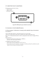
Figure B5
DB9 Connector
Figure B6
JP1 jumpered 2 to 3
Figure B7
JP3 jumpered 1 to 2
Summary of Contents for ACDEF1000-11
Page 2: ...A01 00040 Rev E ...