PowerTec OS1400 Owner'S Manual Download Page 6

POWER SOURCE

Do not connect to the power source until the machine is 

completely assembled. 

The machine is wired for 120 volts, 60 HZ alternating 

current. Before connecting the machine to the power 

source, make sure the switch is in the "OFF" position. 

Running the unit on voltages which are not within range 

may cause overheating and motor burn-out. Heavy loads 

require that voltage at motor terminals be no less than the 

voltage specified on nameplate.

•  Power supply to the motor is controlled by a single pole

  locking rocker switch. Remove the key to prevent 

  unauthorized use.

GROUNDING INSTRUCTIONS

Improper connection of equipment grounding conductor 

can result in the risk of electrical shock. 

•  The machine should be grounded while in use to protect 

   operator from electrical shock. 

•  In the event of an electrical short circuit, grounding 

   reduces the risk of electrical shock by providing an 

   escape wire for the electric current. 

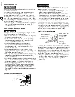
•  This machine is equipped with an approved 

   3-conductor cord rated at 150V and a 3-prong 

   grounding type plug (Figure 5) for your protection 

   against shock hazards. 

•  Grounding plug should be plugged directly into a 

   properly installed and grounded 3-prong grounding-type 

   receptacle, as shown (Figure 5) 

•  The plug must be plugged into an outlet that is properly 

   installed and grounded in accordance with all local 

   codes and ordinances. 

•  

Check with a qualified electrician or service personnel if 

   these instructions are not completely understood or if in 

   doubt as to whether the tool is properly grounded. 

•  

Do not modify plug provided. If it will not fit in outlet, 

   have proper outlet installed by a qualified electrician. 

   Use only 3-wire extension cords, that have 3-prong  

   grounding type plugs and matching 3-conductor 

   receptacles that accept the machine's plug, as show in 

   Figure 5

Do not permit fingers to touch the terminals of plug when 

installing or removing from outlet.

•  Inspect tool cords periodically, and if damaged, have

  repaired by an authorized service facility.

•  The conductor with insulation having an outer surface 

   that is green with or without yellow stripes is the 

   equipment-grounding conductor. If repair or replacement 

   of the electric cord or plug is necessary, do not connect 

   the green (or green and yellow) wire to a live terminal. 

A temporary 3-prong to 2-prong grounding adapter (see

Figure 6) may be used to connect this plug to a matching 

2-conductor receptacle as shown in figure 6. The tempo

-

rary adapter should be used only until a properly ground-

ed outlet can be installed by a qualified electrician. 

In Canada, the use of temporary adapter is not permitted 

by the Canadian Electric Code.  Where permitted, the rigid 

green tab or terminal on the side of the adapter must be 

securely connected to a permanent electrical ground such 

as a properly grounded water pipe, a properly grounded 

outlet box or a properly grounded wire system.

•  Many cover plate screws, water pipes and outlet boxes  

  are not properly grounded. To ensure proper ground,    


grounding means must be tested by a qualified 

  electrician.

Grounded Plug

Grounded Prong

3-Prong Plug

Figure 5 - 3-Prong Receptacle

4

ASSEMBLY

Make Sure This

Is  Connected

To A Known

Ground

2-Prong

Receptacle

Grounding Lug

Adapter

3-Prong Plug

Figure 6 - 3-Prong Receptacle

     WARNING

     WARNING

     WARNING

Summary of Contents for OS1400

Page 1: ...NDLE SANDER QUESTION 1 877 393 7121 13 05 20 Youwill needthismanualfor safetyinstructions operatingprocedures andwarranty Put it and the original sales invoice in a safe dry place for future reference Visit us on the web at www southerntechllc com ...

Page 2: ...CATIONS SAFETY RULES 1 Work Preparation Work Area Preparation Tool Maintenance Tool Operation ASSEMBLY 2 Unpackaging Attach Abrasive Sleeves Onboard Storage Power Source Grounding Instructions Extension Cords Motor Electrical Connections OPERATION 6 Basic Sanding Operation Dust Collection MAINTENANCE 8 Cleaning Lubrication Tool Repairs TROUBLESHOOTING 9 PARTS ILLUSTRATION 10 LIST WARRANTY 12 SECTI...

Page 3: ...ildren and visitors can be injured Make your workshop childproof with padlocks master switches or remove switch keys to prevent any uninten tional use of power tools TOOL MAINTENANCE Turn the machine OFF and disconnect the machine from the power source prior to inspection Maintain all tools and machines in peak condition Keep tools sharp and clean for best and safest performance Follow instruction...

Page 4: ... are present Immediately report missing parts to dealer The sander comes assembled as one unit Additional parts should be located and accounted for before assembling A Table Inserts 6 1 1 2 and 3 B Spindle Knob C Drum Washers 5 1 1 2 and 3 D Spindle Drums 5 1 1 2 and 3 E Abrasive Sleeves 6 1 1 2 and 3 ASSEMBLY 2 Figure 1 Unpacking A B C E D ...

Page 5: ... will not spin loose during operation TO ATTACH 3 ABRASIVE SLEEVES Example 2 Place the 2 table insert over spindle and onto the table The top side of the insert has directional arrows as shown Slide 2 sleeve over the 2 drum first then slide drum with sleeve onto spindle Place 2 drum washer on drum Tighten the knob to secure drum in position Knob and washer must hold the drum securely so that it doe...

Page 6: ...odify plug provided If it will not fit in outlet have proper outlet installed by a qualified electrician Use only 3 wire extension cords that have 3 prong grounding type plugs and matching 3 conductor receptacles that accept the machine s plug as show in Figure 5 Do not permit fingers to touch the terminals of plug when installing or removing from outlet Inspect tool cords periodically and if damaged...

Page 7: ...e machine is assembled with motor and wiring installed The electrical wiring schematic is shown in Figure 8 MOTOR SPECIFICATIONS Horsepower Peak HP 0 4 Voltage 120 Amp 2 6 Hertz 60 Phase Single RPM 1725 ELECTRICAL CONNECTIONS All electrical connections must be performed by a qualified power source while motor is mounted connected recon nected or anytime wiring is inspected Motor and wires are insta...

Page 8: ...e protection or face shield Test operation by hands for clearance and adjust if The drum should trun clockwise Allow drum to come up to full speed before starting sanding Do not attemp to stall motor or reduce speed Do not force the work into the abrasives Keep your hands clear of any moving parts Avoid kickback of the workpiece by sanding in accordance with the directional arrows Never push a sha...

Page 9: ...r best results start with a coarse grit and sand until the surface is uniform Medium grit may then be used to remove scratches from by the coarser grit and finer grit used for the final finishing DUST COLLECTION Refer to Figure 9 A dust collection port has been provided it is located beneath the work table on the rear side of the sander The dust port is sized to fit many commomly used wet dry vacuums ...

Page 10: ...shielded ball bearings in this unit are permanently lubricated at the factory They require no more lubrication A light coat of paste wax on the work table will make it easier to feed the workpiece and prevent rust KEEP TOOL IN REPAIR If power cord is worn cut or damaged in any way do not operate the machine Replace any worn damaged or missing parts Use parts list to order parts Any attempt to repa...

Page 11: ... 1 Too much sawdust builds up 2 Faulty oscillating mechanism 1 Spindle and motor not aligned properly 2 Drum and sleeve not secured properly SOLUTIONS 1 Check power supply for proper voltage 2 Inspect line cord and plug for faulty insulation or shorted connection 3 Inspect connection on motor 4 Inspect connection on motor 5 Replace with correct fuses or circuit breakers 6 Replace switch 1 Reduce w...

Page 12: ...OSCILLATING SPINDLE SANDER PARTS ILLUSTRATION 10 ...

Page 13: ... ø17 2 17 OS1400012 shaft 1 18 OS1400013 A model round flat key 5x5x20L 1 19 OS1400014 Spring 1 20 OS1400015 Flange Bevel Gear 1 21 OS1400016 Bearing 6001 2Z 2 22 OS1400017 Gear Shaft 1 23 OS1400018 Motor Stud 3 24 OS1400019 Flange Straight Gear 1 25 OS1400020 Circlip For Shaft ø12 1 26 OS1400021 Motor 1 27 OS1400022 Sound Insulation Cover 2 28 OS1400023 Diode rectfier bridge 1 29 OS1400024 Flat W...

Page 14: ...purchase This warranty is specific to this tool Southern Technologies LLC reserves the right to repair or replace the defective tool at its discretion HOW TO OBTAIN SERVICE To obtain service for this POWERTEC tool you must return it freight prepaid to an authorized POWERTEC service center for bench top and stationary power tools You may obtain the location of the authorized service center nearest ...

Page 15: ...ect indirect incidental or consequential damages Some states do not allow limitations on how long an implied warranty lasts and or do not allow the exclusion or limitation of incidental or consequential damages so the above limitations may not apply to you This warranty gives you specific legal rights and you may also have other rights which vary from state to state Southern Technologies LLC makes...

Page 16: ...Southern Technologies LLC 206 Terrace Drive Mundelein Illinois 60060 ...

Reviews: