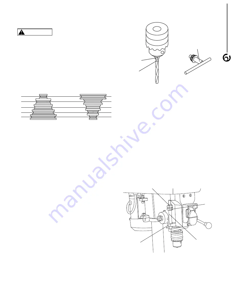
background image

ADJUST SPEEDS


Refer to Figure 13

Turn the switch to “OFF” position and disconnect the 
machine from power source. 

This drill press has  5 speeds: 620 RPM, 
1000RPM, 1720RPM,  2340RPM and 3100RPM. The 
speed is determined by the location of the belt on the 
pulleys. The speed chart shows the pulley configuration 
for each speed. 

INSTALL DRILL BIT

Refer to Figure 14

•  Insert the chuck key. Rotate counterclockwise to loosen 
   the chuck jaws so that the opening is slightly larger than 
   the bit size you intend to use.
•  Insert the smooth end of drill bit all the way into the 
   chuck. Slightly pull back the drill bit by 1/16”. If the spiral 
   groove (flute) of drill bit is still inside the chuck, pull 
   further until the spiral groove is free from chuck 
   jaws’ grip when tighten. 
•  Turn chuck key clockwise to tighten the chuck jaws. 
   Check to see the drill bit is centered and secure in the 
   chuck. 
•  Remember to remove chuck key before operating the 
   machine. 

ADJUST DEPTH STOP

Refer to Figure 15

The depth stop is attached to the quill with hex hut that 
can be lowered or raised on the stud. To set the depth 
stop:
•  Lower the drill bit to the desired height by using the 
   handles. 
•  Hold the feed handle at the desired position. 
•  Use wrench to spin the lower lock nut down to contact 
   the depth stop and lock the nut.
•  Spin the upper nut  against against the lower stop nut 
   and tighten. 
•  The drill bit will stop after traveling the distance on the 
   depth scale. 

7

OPERATION

7

Figure 13

5
4
3
2
1

5-5

4-4

3-3

2-2

1-1

3100

2340

1720

1100

620

5
4
3
2
1

Spindle

Belt

Location RPM

Motor

Figure 14

Chuck Jaws

Drill Bit

Chuck Key

Figure 15

Upper Lock Nut

Depth Stop

Depth Scale

Lower 
Lock Nut

     WARNING

Summary of Contents for DP801

Page 1: ...S QUESTION 1 877 393 7121 11 1221 You will need this manual for safety instructions operating procedures and warranty Put it and the original sales invoice in a safe dry place for future reference Visit us on the web at www southerntechllc com ...

Page 2: ...ble Movement 45 Bevel 360 Swivel Overal Height 22 1 2 Net Weight 35 lbs TABLE OF CONTENTS PRODUCTION SPECIFICATIONS SAFETY RULES 1 Work Preparation Work Area Preparation Tool Maintenance Tool Operation ASSEMBLY 2 OPERATION 6 Description Safety Precautions ON OFF Switch Adjust Table Height and Tilt Table Adjust Speed Install Drill Bit Adjust Depth Stop Adjust Belt Tension MAINTENANCE 8 Cleaning Lub...

Page 3: ...r shop is a potentially dangerous environment Children and visitors can be injured Make your workshop childproof with padlocks master switches or remove switch keys to prevent any uninten tional use of power tools TOOL MAINTENANCE Turn the machine OFF and disconnect the machine from the power source prior to inspection Maintain all tools and machines in peak condition Keep tools sharp and clean fo...

Page 4: ...ier immediately Check for complete part list Contact Customer Service Center immediately for missing parts Locate the following parts before assembling A Head Assembly B Table C Base D Column Assembly E Feed Handles 3 F Hex Wrench G Hex Bolts 3 H Spring Washers 3 I Chuck Key J Chuck ASSEMBLY 2 Figure 1 Unpacking A B E F G H I J C D ...

Page 5: ...e threaded hole at the rear of the table assembly To lock table in position tighten lock handle to secure table Figure 3 INSTALL THE DRILL PRESS HEAD Refer to Figure 4 Position and slide the head over the column Carefully rotate the head on the column so it is aligned with the base Secure the drill press head with two lock set screws using the hex wrench Figure 4 INSTALL HANDLES Refer to Figure 5 ...

Page 6: ...ate Power supply to the motor is controlled by a locking rocker switch Remove the key to prevent unauthorized use GROUNDING INSTRUCTIONS Improper connection of equipment grounding conductor can result in the risk of electrical shock The machine should be grounded while in use to protect operator from electrical shock In the event of an electrical short circuit grounding reduces the risk of electri...

Page 7: ...green tab or terminal on the side of the adapter must be securely connected to a permanent electrical ground such as a properly grounded water pipe a properly grounded outlet box or a properly grounded wire system Many cover plate screws water pipes and outlet boxes are not properly grounded To ensure proper ground grounding means must be tested by a qualified electrician EXTENSION CORDS Use prope...

Page 8: ...ch is located on the front of drill press head To turn the machine ON pull the switch to the up position To turn the machine OFF push the switch to the down position NOTE When the machine is not in use the machine should be locked in the OFF position to prevent unau thorized use To lock the machine turn the switch to OFF position Pull the key out The switch cannot be turned on without the key If t...

Page 9: ...huck jaws grip when tighten Turn chuck key clockwise to tighten the chuck jaws Check to see the drill bit is centered and secure in the chuck Remember to remove chuck key before operating the machine ADJUST DEPTH STOP Refer to Figure 15 The depth stop is attached to the quill with hex hut that can be lowered or raised on the stud To set the depth stop Lower the drill bit to the desired height by u...

Page 10: ...he motor in position Turn the switch to OFF position and disconnect the machine from power source before servicing or disassembling any components CLEANING Keep machine and workplace clean Avoid accumulation of sawdust on the tool Be certain motor is kept clean and free of dust Use soap and water to clean painted parts rubber parts and plastic guards LUBRICATION A light coat of paste wax on the wo...

Page 11: ...ndle pulley looses 2 Motor pulley looses 3 Incorrect belt tension 1 Drill bit is dull 2 Incorrect speed 3 Chips in the hole SOLUTIONS 1 Check power supply for proper voltage 2 Inspect line cord and plug for faulty insulation or shorted connection 3 Inspect connection on motor 4 Inspect connection on motor 5 Replace with correct fuses or circuit breakers 6 Replace switch 7 Replace capacitor 1 Reduc...

Page 12: ...8 DRILL PRESS PARTS ILLUSTRATION 10 ...

Page 13: ...4 SPRING WASHER 3 85 DP801085 SCREW CAP M6 1 Key No Part No Part Name Qty Key No Part No Part Name Qty 1 DP801001 KNOB 1 2 DP801002 NUT M5 2 3 DP801003 WIRE PRESS BUCKLE 2 4 DP801004 PAN HEAD SCREW M6 8 1 5 DP801005 PULLEY HOUSING 1 6 DP801006 NUT M5 1 7 DP801007 LINE CORD CLAMP 1 8 DP801008 COLUMN HEAD SCREW M5x12 1 9 DP801009 PAN HEAD SCREW M5 8L 2 10 DP801010 COLUMN HEAD SCREW M6 10L 4 11 DP801...

Page 14: ...the date of purchase This warranty is specific to this tool Southern Technologies LLC reserves the right to repair or replace the defective tool at its discretion HOW TO OBTAIN SERVICE To obtain service for this POWERTEC tool you must return it freight prepaid to an authorized POWERTEC service center for bench top and stationary power tools You may obtain the location of the authorized service cen...

Page 15: ... indirect incidental or consequential damages Some states do not allow limitations on how long an implied warranty lasts and or do not allow the exclusion or limitation of incidental or consequential damages so the above limitations may not apply to you This warranty gives you specific legal rights and you may also have other rights which vary from state to state Southern Technologies LLC makes no...

Page 16: ...Southern Technologies LLC 206 Terrace Drive Mundelein Illinois 60060 ...

Reviews: