background image

•   Push the Limit Block Shaft (3) toward the fence. Place 
   the Limit plate (1) of the Fence Bracket Assembly into 
   the Limit Block Rear Slot (2).  
•   Pull the fence toward perpendicular to the table (90°) 
   position. The fence will hit and be stopped by Limit 
   Block Shaft (3). Now tighten the Fence Tilting Handle 
   (6).  The Fence is at 90° position.

To set the inward 45° stop: 
•   Position the fence on the bed. Place sliding handle (7) in 
   locked position. Loosen the fence tilting handle (6).  
•   Pull the top of the fence toward the table. It will hit and 
   stopped by the inward stop bolt (4). Now tighten the 
   fence tilting handle (6). The fence is at inward 45° 
   position.  


To set the outward 45° stop: 
•   Position the fence on the bed. Place sliding handle (7) in 
   locked position. Loosen the fence tilting handle (6).  
•   Pull out the limit block shaft (3) so it will not limit outward 
   movement of the fence.   
•   Pull the top of the fence outward. It will hit and stopped 
   by the outward stop bolt (8). Now tighten the fence tilting 
   handle (6). The fence is at outward 45° position.  

CHECK BLADE OUTFEED TABLE 

ALIGNMENT


Turn the switch in “OFF” position and disconnect the 
jointer from the power source.  
Do not touch the blade cutting edge at any time.  
The blades have been adjusted in the factory and should 
require no adjustment. Nevertheless, the blades can 
become out of alignment during shipping and handling. 
For accurate cutting, the blades must be at the same level 
with the outfeed table.  
•   To adjust the blades, position a straight edge on the 
   outfeed table and have it extend over the cutterhead.  
•   Gently rotate the cutterhead under the straight edge. 
   The blades should just touch the straight edge by a hair. 
   The blades may brush the straight edge and pull it 
   forward slightly (No more than 1/8” on each blade pass).  
   If a blade does not touch the straight edge at all, it is too 
   low. If a blade pulls forward the straight edge more than 
   1/8”, it is too high.   
•   Check blade height at both ends of the blade to see if it 
   is level from side to side.  
•   Check each blade using the same procedure.  

ADJUST THE HEIGHT OF THE CUTTERHEAD 

BLADES:

Turn the switch to OFF position and diconnect the ma-
chine from power source. 
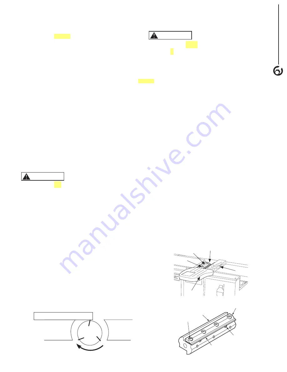
Refer to Figure 12 and 13  
•   Pull open the blade guard (4) and block it in open 
   position with a piece of wood (3).  Now the cutterhead 
   (1) is fully exposed.  
•   Locate the blade lock screws (5) and jack screws (6) on 
   the cutterhead (1) 
•   Loosen the four blade lock screws (5) and the two jack 
   screws (6) with enclosed 4mm hex wrench.  
•   Use a wood block to push down the blade (7) gently 
   until the blade edge is slightly below the straightedge 
   (see Figure 11).  
•   Turn each jack screw (6) clockwise, 1/8 of a turn at a 
   time, until the edge of the blade just touches the straight 
   edge by a hair.  Adjust the blade at both ends so they 
   are even from side to side. 
•   With the screws are partially loose, gently rotate the 
   cutterhead (1) under the straight edge. The blades (7) 
   may brush the straight edge and pull it forward slightly 
   (No more than 1/8” on each blade pass).  If a blade (7) 
   does not touch the straight edge at all, it is too low. If a 
   blade pulls forward the straight edge more than 1/8”, it 
   is too high. Adjust the jack screws until the blade height 
   is correct at both ends.  
•   Tighten each blade lock screws (5) and jack screws (6) 
   firmly. 
•   Adjust each blade using the same procedure. 
•   Return the blade guard (4) to its original position.  

     WARNING

Figure 11 - Cutterhead Alignment Setup 

     WARNING

Figure 12 - Block Blade Guard

Figure 13 - Cutterhead Illutration 

OPERA

TION

7

Outfeed
Table

Infeed
Table

CUTTER HEAD

Straight Edge

1

2

3

4

5

1

2

6

7

5

the "OFF"

the

(remove "toward")

be

to the

Summary of Contents for BJ600

Page 1: ...N DUST COLLECTION QUESTION 1 877 393 7121 09 0909 You will need this manual for safety instructions operating procedures and warranty Put it and the original sales invoice in a safe dry place for future reference Visit us on the web at www southerntechllc com ...

Page 2: ... Power Source Grounding Instructions Extension Cords Motor Electrical Connections OPERATION 6 Description Specifications Safety Precautions Position Fence Check Blade Outfeed Table Alignment Adjust the Height of the Cutterhead Blades Adjust the Depth of Cut Measure the Depth of Cut Check the Blade Guard On Off Switch Feed Direction Feed the Workpiece Use Hold Down Push Blocks Bevel and Chamfer MAI...

Page 3: ...r shop is a poten tially dangerous environment Children and visitors can be injured Make your workshop childproof with padlocks master switches or remove switch keys to prevent any uninten tional use of power tools TOOL MAINTENANCE Turn the machine OFF and disconnect the machine from the power source prior to inspection Maintain all tools and machines in peak condition Keep tools sharp and clean f...

Page 4: ...if damage has occurred A Jointer bed assembly B Fence C Fence support D Fence bracket assembly E Locking plate assembly F Fence sliding handle with spacer G Push blocks 2 H Fence tilting handle with spacer I Dust chute J Dust Collection Bag K Dust Collection Clamp L Dust Collection Wire Hardware bag includes 8 1 25 x 25 mm socket head bolts 6 8mm lock washer 6 4 and 6mm hex wrench 6 1 0 x 25mm pan...

Page 5: ...e fence forward so that the fence contacts the cutterhead guard At this position the cutterhead is completely covered by cutterhead guard Install fence tilting handle H with spacer through right link and thread into left link Figure 3 ATTACH DUST COLLECTION BAG Refer to Figure 1 and 4 Install the Dust Chute I by slip it over the Dust Port Tighten the screw on the Dust Chute I Insert Dust Bag Wire ...

Page 6: ...e Power supply to the motor is controlled by a locking rocker switch Remove the key to prevent unauthorized use GROUNDING INSTRUCTIONS Improper connection of equipment grounding conductor can result in the risk of electrical shock The machine should be grounded while in use to protect operator from electrical shock In the event of an electrical short circuit grounding reduces the risk of electrica...

Page 7: ...ing an extension cord make sure to use one heavy enough to carry the current of the machine An undersized cord will cause a drop in the voltage resulting in loss of power and overheating Use the table to determine the minimum wire size A W G extension cord Extension Cord Length Wire Size A W G Up to 25 ft 18 25 to 50 ft 16 NOTE Using extension cords over 50 ft long is not recommended MOTOR Jointer...

Page 8: ...cutterhead Never make cuts deeper than 1 8 3 2mm deep to prevent kickback Do not force cut Slowing or stalling will overheat motor Do not perform jointer operations on workpiece shorter than 10 narrower than 3 4 or less than 1 2 thick Properly support long or wide workpieces Use hold down push blocks for jointing any workpiece lower than the fence Do not perform a workpiece that is warped contains...

Page 9: ... and pull it forward slightly No more than 1 8 on each blade pass If a blade does not touch the straight edge at all it is too low If a blade pulls forward the straight edge more than 1 8 it is too high Check blade height at both ends of the blade to see if it is level from side to side Check each blade using the same procedure ADJUST THE HEIGHT OF THE CUTTERHEAD BLADES Turn the switch to OFF posi...

Page 10: ...se To turn the jointer ON pull the switch to the up position To turn the sander OFF push the switch to the down position NOTE When the machine is not in use the switch should be locked in the OFF position to prevent unauthorized use To lock the machine turn the switch to OFF position Pull the key out The switch can t be turned on without the key If the key is removed when the switch is at the ON p...

Page 11: ...he leading hand and the leading hand becomes the trailing hand Repeat this until the entire workpiece passes through the cuttinghead While alternating your hands try to keep firm control of the workpiece and keep the feed speed constant Surface plane on the jointer The concave face to the workpiece is the surface planed flat with the jointer Edge jointer on the jointer The concave edge of the work...

Page 12: ...tect the table top so the sharpening stone would not scratch the table surface Adjust the infeed table so the sharpening stone can reach beveled edge of the blade Gently grind the stone against the blade edge from side to side until the blade is sharp again Repeat the same procedure on each blade If the blades can not be sharpened this way they need to be replaced or removed and reground If a blad...

Page 13: ... set Two brush assemblies only Replace with new parts only To inspect motor brushes unscrew brush caps on the sides of motor There are two caps one on each side of motor Remove brush assembly from motor Replace motor brushes if the length of carbon has been worn to less than 3 8 or if the springs are worn or if the motor does not run smoothly Replace with new motor brush assembly Replace the brush...

Page 14: ...rain due to blades cutting against grain 4 The cut is too deep CORRECTIVE ACTION 1 Check power supply for proper voltage 2 Inspect line cord and plug for faulty insulation or shorted connection 3 Inspect connection on motor 4 Inspect connection on motor 5 Replace with correct fuses or circuit breakers 6 Replace switch 7 Replace capacitor 1 Reduce workload on the power supply 2 Check power supply f...

Page 15: ...6 BENCH JOINTER PARTS ILLUSTRATION 13 ...

Page 16: ...NCH 1 59 BJ600059 4MM WRENCH 1 60 BJ600060 DUST COLLECTION BAG 1 61 BJ600061 DUST COLLECTION WIRE 1 62 BJ600062 DUST CHUTE 1 63 BJ600063 6 20MM PAN HEAD SCREW 1 64 BJ600064 5 12MM SOCKET HEAD BOLT 1 65 BJ600065 WASHER 5MM 1 66 BJ600066 CHIP COLLECTOR 1 67 BJ600067 SPONGE 1 68 BJ600068 CHIP EXHAUST 1 69 BJ600069 5MM FLAT WASHER 3 70 BJ600070 IMPELLER 1 71 BJ600071 26 EEX RET RING 1 72 BJ600072 CHIP...

Page 17: ... This warranty is specific to this tool Southern Technologies LLC reserves the right to repair or replace the defective tool at its discretion HOW TO OBTAIN SERVICE To obtain service for this POWERTEC tool you must return it freight prepaid to an authorized POWERTEC service center for bench top and stationary power tools You may obtain the location of the authorized service center nearest you by c...

Page 18: ...irect indirect incidental or consequential damages Some states do not allow limitations on how long an implied warranty lasts and or do not allow the exclusion or limitation of incidental or consequential damages so the above limitations may not apply to you This warranty gives you specific legal rights and you may also have other rights which vary from state to state Southern Technologies LLC mak...

Page 19: ...Southern Technologies LLC 206 Terrace Drive Mundelein Illinois 60060 ...

Reviews: