4
ASSEMBLY
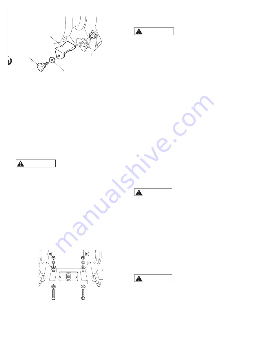
Figure 5
Tool Rest
Tool Rest
Support
Large Flat
Washer
Tool Rest
Knob
• Repeat to assemble the other tool rest.
• Adjust the tool rest assembly.
• Loosen the tool rest support knob and slide the tool
rest assembly in or out to maintain a distance of 1/8"
(3.18 mm) or less between the grinding wheel and
inside edge of the tool rest. When the tool rest is
positioned correctly, tighten the locking knobs. As the
wheel wears the tool rest assembly will need to be
adjusted, check this adjustment often.
• Loosen the tool rest locking knob and adjust the tool
rest to the desired angle, tighten the locking knob.
BENCH MOUNTING
Refer to Figure 6
WARNING
To avoid serious injury, secure the bench grinder to a solid
work surface. If the Grinder is not permanently mounted
to a work surface, clamp the grinder’s base to a table or
board/plywood. Make sure the clamps do not interfere
with the tool rests, wheels or obstruct the movement of
the user and the material being ground during use. If
the bench grinder is not securely mounted, it will have
the ability to move or tip over during grinding operations
and possibly cause the operator’s fingers to contact the
grinding wheels.
Use the mounting holes in the base of the grinder to
firmly attach grinder to a solid work surface or grinder
stand (mounting hardware and stand not included). See
Figure 6.
Figure 6
CHANGING THE GRINDING WHEEL
Refer to Figure 7
WARNING
Always place the ON/OFF switch in the OFF position
and unplug the power cord from its power source
before performing any assembly or adjustment.
Failure to do so could result in accidental starting resulting
in possible serious personal injury.
The grinding wheels will wear and need to be replaced
occasionally.
• Rotate the eye shield up to access the tool rest.
• Loosen the tool rest locking knob and rotate the tool rest
away from the grinding wheel.
• Remove the fasteners securing the outer wheel guard in
place, remove the outer wheel guard.
• Place a wood wedge between the grinding wheel and
the wheel guard to keep the shaft from turning.
• Remove the wheel hex nut.
NOTE:
The left hand wheel hex nut is left hand threaded
and is loosened by rotating it clockwise. The right hand
wheel hex nut is right hand threaded and is loosened by
rotating it counter-clockwise.
• Remove the outer wheel flange and then the grinding
wheel from the shaft.
NOTE:
If using an optional accessory (such as a wire
or buffing wheel) one or more spacers (not included)
may need to be added before the inner wheel flange so
the wheel hex nut tightens correctly. Remove the inner
wheel flange to add optional washers. ALWAYS use the
wheel flanges the come with the grinder when using a
wire or buffing wheel.
CAUTION
The new grinding wheel to be put onto the bench grinder
must have a higher R.P.M. rating than the grinder’s motor.
The new grinding wheel must have the correct 8" outer
wheel diameter and 5/8" bore diameter as original wheels.
DO NOT remove the labels on the side of the grinding
wheel. These labels or fiber discs help spread the holding
pressure of the tightened nuts on the grinding wheel
flanges.
• Replace the wheel, outer wheel flange and wheel hex
nut.
NOTE:
The left hand wheel hex nut is left hand threaded
and is tightened by rotating it counter-clockwise. The
right hand wheel hex nut is right hand threaded and is
tightened by rotating it clockwise.
CAUTION
DO NOT OVER TIGHTEN
the wheel hex nut as this may
damage the grinding wheel, wheel flanges and cause
serious injury to the operator.
• Replace the wheel guard and secure with the fasteners
removed earlier.
Summary of Contents for BGSS801
Page 10: ...8 SLOW SPEED GRINDER PARTS ILLUSTRATION 8 PARTS LIST 8...
Page 13: ...NOTE...
Page 14: ...NOTE...
Page 15: ...NOTE...
Page 16: ......


