background image

8

Skid Shoe Installation and
Adjustment

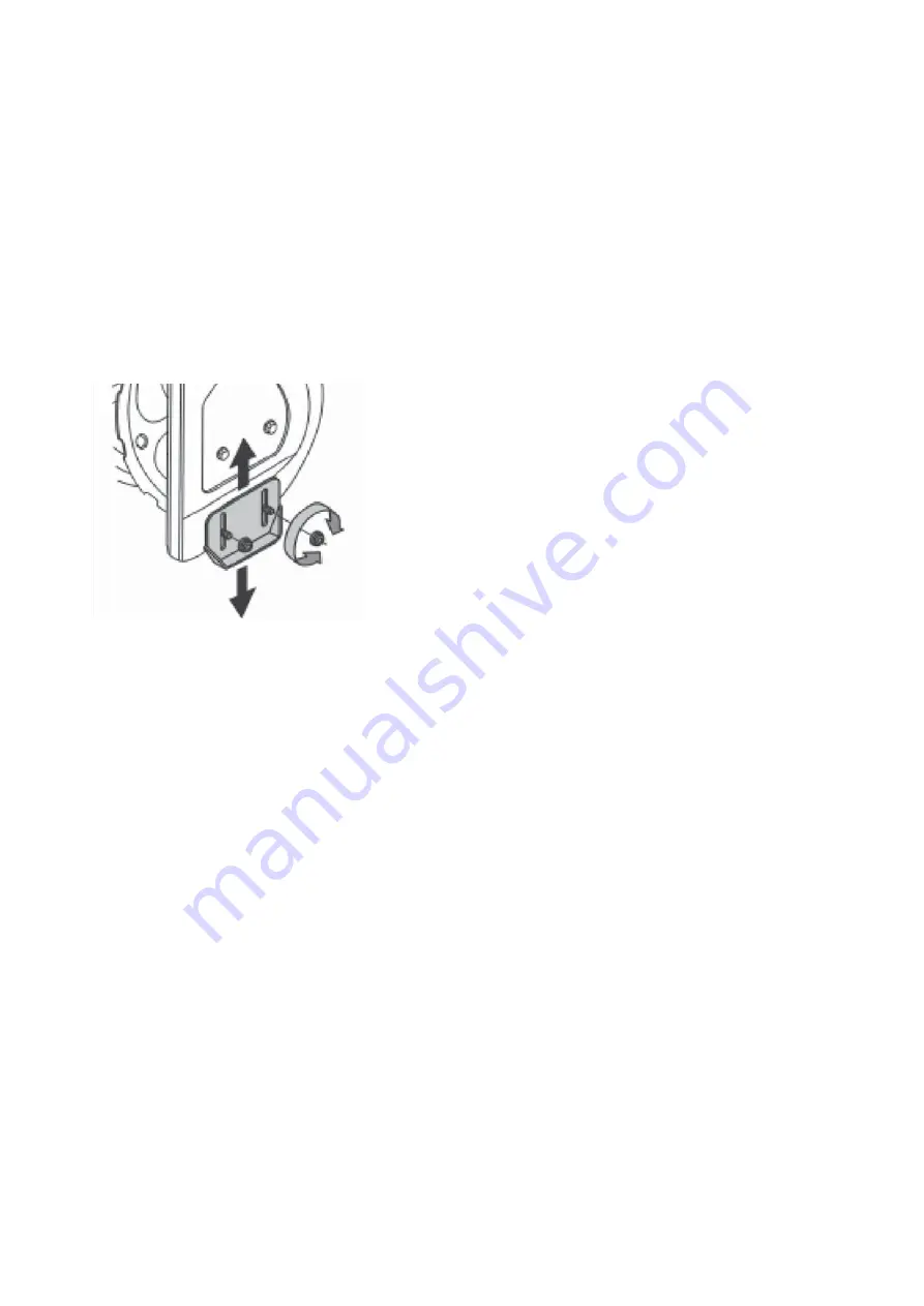
1. Locate the pair of skid shoes from parts bag

and remove the bolts.

2. Loosely install the skid shoes using the bolts

,

washers and hex nuts as shown on each side
of the auger housing.

Adjustment of the skid shoes sets the height
above the ground at which the auger shave plate
operates. For clearing snow from concrete,
asphalt, and other smooth surfaces, set the
auger shave plate so that the bottom of the plate
just scrapes the ground. For

Clearing snow

from gravel, dirt, and other rough surfaces

set the auger shave plate slightly above the ground to

avoid dirt and gravel from entering the auger. The
optimal height of the plate will vary depending on
the type of surface being cleared. Surfaces with
larger gravel or stones require a higher shave
plate setting.

3. Move the Snow Thrower to a solid, smooth,

and level surface.

4. Place a spacer board on the ground

underneath the auger shave plate between
the skid shoes. The thickness of the board
should be the same as the height above the
ground you wish to raise the auger shave
plate. The skid shoes should not touch the
board.

5. With the two (2) nuts loose allow the skid shoe

to slide to the ground then tighten the nuts to
secure the skid shoe.

OPERATION

PLEASE REFER TO ENGINE MANUAL
(SEPARATE DOCUMENT) FOR ENGINE
OPERATION INSTRUCTIONS.

The following section describes steps to prepare
your Snow Thrower for use. If after reading this
section, if you are unsure about how to perform
any of the steps please call
1-800-791-9458 for customer service. Failure to
perform these steps properly can damage your
Snow Thrower or shorten its life.

Review the SAFETY section in this manual and
the ENGINE manual before operating the engine
and snow thrower.

WARNING! Keep the area of operation free
from foreign objects that can be thrown by the
auger and/or impeller blades. Perform a
thorough inspection of the area since some
objects may be hidden from view by
surrounding snow. If the Snow Thrower hits
an obstruction or picks up a foreign object
during use, stop the Snow Thrower, remove
the obstruction, and inspect it for damage.
Repair or replace any damaged parts before
restarting and operating you Snow Thrower.

‡

Keep children, pets, and bystanders away from the
area of operation. Be aware that the normal noise of
the Snow Thrower when turned on may make it
difficult for you to hear approaching people.

NOTICE: Make sure all fasteners are tightened
before starting the machine.

Summary of Contents for DB7103-24

Page 1: ...plosion if used near combustible material or fluid Only use when the engine s exhaust system is equipped with a spark arrester meeting applicable local or state laws if any The spark arrester shall be maintained in effective working order by operator Questions problems missing parts If you have questions or need technical support call the Amerisun customer service department at 1 800 791 9458 or v...

Page 2: ...f inlet and discharge Openings while machine is running There are rotating blades inside WRNING THROWN OBJECTS This machine may pick up and throw Objects which can cause serious personal Injury Do not touch any rotating part before machine stops 30 WARNING ROTATING BLADES Keep hands out of inlet and discharge Openings while machine is running There are rotating blades inside Waste electrical produ...

Page 3: ...ipping or falling especially when operating in reverse Preparation Thoroughly inspect the area where the equipment is to be used Remove all doormats newspapers sleds boards wires branches and other foreign object which could be tripped over or thrown by the auger impeller Always wear safety glasses or eye shields during operation and while performing an adjustment or repair to protect your eyes th...

Page 4: ...r is a safety device Never bypass its operation Doing so makes the machine unsafe and may cause personal injury The control levers must operate easily in both directions and automatically return to the disengaged position when released Never operate with a missing or damaged chute assembly Keep all safety devices in place and working Never run an engine indoors or in a poorly ventilated area Engin...

Page 5: ...ufacturers OEM parts only Use of parts which do not meet the original equipment specifications may lead to improper performance and compromise safety Check control levels periodically to verify they engage and disengage properly and adjust if necessary Refer to the adjustment section in this operator s manual for instructions Maintain or replace safety and instruction labels as necessary Observe p...

Page 6: ... Engine Displacement 208cc 4 stroke A Drive Control Handle E Engine I Snow Ice Clean Out Tool B Speed Control Lever F Skid Shoe J Chute Assembly C Auger Control Handle G Augers K Chute Deflector Lever r e l l e p m I H e l d n a H n o i t a t o R e t u h C D A C K B D J I H G F E For a complete parts breakdown go to www amerisuninc com L L Light ...

Page 7: ...mbly and chute opening when snow and ice become lodged WARNING Never use your hands to clear a clogged chute assembly Shut off engine and remain behind handles until all moving parts have stopped before unclogging J Chute Assembly The chute provides a discharge path for snow being thrown The chute is adjustable K Chute Deflector Lever The angle of the chute deflector controls the discharge distanc...

Page 8: ...rs and bolts NOTICE Do not bend or kink the control cables The cables should be routed under the handle assembly and not wrapped around the handle or knobs The cables must move freely and not bind 3 Secure the speed control cables to the handle with provided clips Note Do not secure the auger or drive control cables with the clips Chute Assembly 1 Install the discharge chute onto the chute flange ...

Page 9: ...wo 2 nuts loose allow the skid shoe to slide to the ground then tighten the nuts to secure the skid shoe OPERATION PLEASE REFER TO ENGINE MANUAL SEPARATE DOCUMENT FOR ENGINE OPERATION INSTRUCTIONS The following section describes steps to prepare your Snow Thrower for use If after reading this section if you are unsure about how to perform any of the steps please call 1 800 791 9458 for customer se...

Page 10: ... push down on the handle to raise the scraper at the base of the unit above the pebbles or gravel Pre Operation Inspection IMPORTANT Before using your Snow Thrower for the first time check the following Have you read and followed all setup and operation procedures for the engine as outlined in the ENGINE manual Has the engine been filled with oil to the proper level Are all snow thrower components...

Page 11: ... cause serious damage and severe bodily injury Always point the discharge chute in the opposite direction from potential hazards The discharge chute can be adjusted 180º by rotating the chute rotation handle Rotate the chute rotation handle clockwise to move the discharge chute to the left counterclockwise to move the chute to the right Chute Discharge Angle Adjustment WARNING Always disengage the...

Page 12: ...emperature humidity levels and overall climate conditions including actual snow conditions there may be no 100 solution as snow may be too wet or compacted to move or throw Wet snow will tend to clog and stick more to the augers and chute Keep the auger engaged as much as possible when clearing wet snow to help prevent clogging WARNING If snow is filled with foreign material damage to the snow thr...

Page 13: ... to a person s body parts Even if you do not see the auger or impeller rotating it may start at any time if the engine is running The chute clean out tool is fastened to the top of the auger housing with a mounting clip and a cable tie at the factory Cut the cable tie before operating the snow thrower 1 Always turn OFF the engine before attempting to clear any clogs or jams 2 Keep hands and feet a...

Page 14: ...re from the spark plug to ensure the engine cannot accidently start Never adjust cable tension with the engine running The drive control cable is located on the right side when standing behind the snow blower and is made up of an upper and lower cable connected by an adjustment plate The adjustment plate is located in line with the cable below the control handle and is covered by a black plastic s...

Page 15: ...left one cable is pulled and one is pushed Depending on if the cable setting is biased towards forward or reverse adjustment of the cables will vary To adjust the cables one cable should be moved up and the other down equally in their respective brackets until there is a positive direction change when the lever is shifted between F1 and R1 The middle position between these two settings is neutral ...

Page 16: ... proper operating tension for a typical drive is the lowest tension at which the belt will not slip under a loaded condition 1 Drive Control Engagement Handle 2 Drive Speed Control Lever 3 Auger Control Engagement Handle 4 Chute Rotation Crank Handle 5 Drive Speed Cables 6 Auger Control Cable 7 Drive Control Cable 8 Chute Deflector Control Handle The auger cable is located on the left side when st...

Page 17: ...y is not engaging the belt There should be no auger movement with the auger handle released If the auger is turning when the auger handle is released loosen the belt tension by readjusting the cable as necessary Do not over tension the cable Auger Belt Removal WARNING Entanglement Hazard Before performing any service procedures make sure the engine is off and remove the spark plug wire from the sp...

Page 18: ...e belt to allow removal of the belt 1 Auger Brake 8 Remove the auger belt Auger Belt Installation WARNING Entanglement Hazard Before performing any service procedures make sure the engine is off and remove the spark plug wire from the spark plug to ensure the engine cannot accidently start NOTICE Before installing the auger belt see Auger Belt and Related Component Inspection and repair or replace...

Page 19: ...e loose enough to allow the belt to spin freely but not allow the belt to jump off the pulley 6 Connect the lower auger cable to the cable adjustment plate 7 Adjust auger belt tension see Auger Belt Tension Adjustment WARNING Ensure the belt cover is installed and all safety guards are in place before the engine is started and at all times when the engine or machine are operating 8 Install belt co...

Page 20: ...improper installation Handle damaged or binding at pivot Storage WARNING Never store your Snow Thrower for extended periods of time with fuel in the tank Fuel stabilizer can be added to the fuel to extend its shelf life for storage Store the unit in a locked dry place out of the reach of children to prevent unauthorized use or damage Cover loosely with a tarp for added protection Cleaning 1 To cle...

Page 21: ...o high 12 Drain oil and put in 16 ounces of oil 13 Internal engine problem 13 See Engine Operator s manual contact service center or engine Engine recoil starter will not pull out hard to pull 1 Frozen recoil starter or engine too cold to turn over 1 Move snow blower to warm space and allow it to warm up 1 Extension cord is not properly attached to electric starter terminal 1 Re insert extension c...

Page 22: ...6 Spark plug wire loose 6 Connect and tighten spark plug wire 7 Faulty spark plug 7 Clean adjust gap or replace spark plug see Engine Operator s manual 8 Gas cap vent hole plugged 8 Remove ice and snow from gas cap check to make sure gasket not covering vent hole 9 Engine oil over filled 9 Drain oil to proper level Oil should not be above the top 2 threads of LOWER fill plug 10 Engine oil level lo...

Page 23: ... forward or reverse 1 Speed control cables misajusted loose damaged or binding 1 Check speed control lever and cables for damage or loose or missing parts Repair or replace parts as needed Adjust drive speed control cables see Drive Speed Control Cables Adjustment 1 Drive control cable binding won t release 1 Repair replace cable as necessary 2 Friction drive wheel return spring broken or missing ...

Page 24: ...k or binding 2 Repair or replace tension arm as necessary 3 Auger tension pulley arm or pulley misaligned or damaged 3 Repair replace or align tension arm and or pulley as necessary 4 Foreign material on pulleys and belt oil grease dirt etc 4 Clean belt and pulleys as necessary replace belt if necessary 5 Auger pulleys misaligned loose damaged or bent 5 Replace or align pulleys as necessary 6 Inco...

Page 25: ...ction with the use of PowerSmart Products covered by this warranty including any cost or expense of providing substitute equipment or service during reasonable periods of mal function or non use pending completion of repairs under this warranty Transportation to and from the services center is the responsibility of the consumer Some states do not allow exclusions of incidental or consequential dam...

Reviews: