POWX0761
EN
Copyright © 2008 VARO
P a g e
|
17
www.varo.com
9.10
Setting up the tool in Mitre saw mode (Fig. 50)
WARNING: Be sure to install the lower blade guard C before using the tool
in Mitre saw mode.
To change the set up from table saw mode to Mitre saw mode, reverse the procedure of the
section titled “Setting up the tool in table saw mode”.
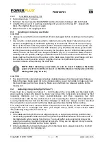
9.10.1
Removing the top blade guard
Push the push button of the top blade guard to its side surface and then just take away the top
blade guard upward with the button depressed.
9.10.2
Installing the lower blade guard C
Place the lower blade guard C on the table so that it fits in the slot of the table and tightening
the clamping screw firmly.
9.10.3
Turning over the tool
Refer to the same titled section i
n the “Setting up the tool in table saw mode”.
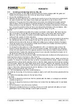
9.10.4
Releasing the tool head from fully lowered position
While holding the handle, pull the stopper pin in the direction of arrow A, turn it to the angle of
90° in the direction of arrow B with the stopper pin pulled and then raise the handle slowly.
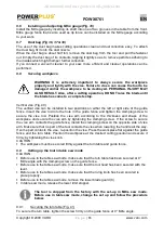
9.10.5
Repositioning riving knife (Fig. 51)
The position of riving knife (Fig. 51-A) should be changed as follows.
(1) Loosen the clamping nut and hold the lower blade guard A using its lug by hand. (Fig. 51-B)
(2) While holding the lower blade guard A, pull the riving knife so that it turns and pivot it to the
position in the direction of arrow. (Fig. 51-C)
(3) With the riving knife held in that position, return the lower blade guard A to the original
position and tighten the clamping nut securely. (Fig. 51-D & E)
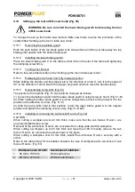
9.10.6
Installing or removing the sub fences R and L (Fig. 52)
CAUTION:
When cutting a workpiece over 20 mm thick, make sure that the sub fences R and L are
securely installed with a screw.
Removal of the sub fences R and L are convenient for cutting wide and thin workpiece.
When cutting a workpiece up to 20 mm thick and more than 180 mm wide, remove the sub
fences R and L by removing the screw shown in the figure.
When cutting a workpiece over 20 mm thick, install the sub fences R and L securely with a
screw.
Refer to the table below for the relation between the size of workpiece and use/unuse of sub
fences R and L. (Fig. 53)
Workpiece size (H x W)
Use/Unuse of subfence
1
68 mm x 155 mm
With sub fences
2
20 mm x 210 mm
Without sub fences
All manuals and user guides at all-guides.com


