8
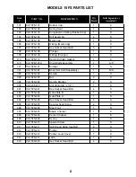
Assemblies, Kits & Accessories
ITEM # PART NO.
DESCRIPTION
QTY. REQ’D
A-2
09-445-29737
5/8” Adapter Pad
1
A-3
09-445-29738
3/4” Adapter Pad
1
A-4
09-445-29757A
6 Oz. Air Tool Oil
1
A-5
09-15FS-120A
DRIVE BLADE ASSEMBLY:
Whole assembly is necessary, individual parts not
sold separately.
1
A-6
06-99606
15FS POWER ROLLER CONVERSION KIT
1
A-7
09-50P3104A
9MM BEARINGS W/ MOLDED COVERS (SET
OF 2)
1
A-8
09-RB15FSA
COMPLETE ROLLER SET (4 LRG R 2
9MM ROLLER)
1
15FS PowerStapler Parts Continued... FLEX Foot operation
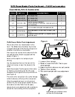
FLEX Power Roller Foot Adjustment:
Wood varies from one manufacturer to the
next. The different wood pro
fi
les may be due
to height and length of the
fl
ooring tongue and
whether or not there is a nail pocket.
First, loosen the two hex bolts under the FLEX
foot with the Allen Wrench supplied with the
stapler. (Figure 1.)
Next, set the stapler on a sample of your
fl
ooring.
Use the adjustment lever at the back of the
roller foot to raise or lower the stapler to the
wood.
Match the Adapter Foot triangle & 9mm rollers
so that they are pointing into the 90° angle
created by the tongue and the top of the wood
(see Figure 2).
For wood with a nail pocket, line up the triangle
& 9mm rollers so at the top of the nail pocket.
When the adjustment lever is in the correct
position for your wood sample, tighten the two
hex bolts to lock the FLEX foot into place.
Always check your adjustment with a sample to
ensure the nail is driving into the nail pocket.
Figure 2.
Hex Allen Wrench
FLEX Foot Adjustment Lever
1. Loosen 2 hex screws.
2. Raise or lower the FLEX Foot to your
wood sample.
3. Match the 9mm rollers to the nail pocket.
4. Tighten 2 hex screws.
5. Test wood sample with new adjustment.
Figure 1.
Adjust FLEX lever so the 9mm rollers
are above the
fl
ooring tongue


