


第 6 页 共 16 页
keys
and
keys
to choice the need to modify number of segment, use
keys
and
keys to modify number of needle in multi-segment sewing stitch setup status.
·
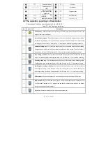
W sewing mode
: Press
key, constant-stitch sewing icon
is lightened in LCD area.
LCD
is W sewing setup status. You may use
keys and
keys to
choice needle in A area and set rang 1-99 stitches; use
keys and
keys to choice
needle in B area and set rang 1-99 stitches. Press
key, can be used to choice A B D segment,
LCD
, use
keys and
keys to choice needle in B area and set rang 1-99
stitches.
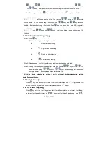
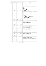
3.1.2 Start/End back tacking setup
:
Step 1: Press
key
Start back tacking has following four modes:
None start back tacking
Single start back tacking
Double start back tacking
Four start back tacking
Step 2: Stop pressing to confirm, then this back tacking mode has been selected.
Step 3: Change the corresponding parameters A values by using
keys
and
keys
and B values by using
keys
and
keys. The value range is 1-99 stitches.
It set pin number to be completed before star back tacking.
Note: End back tacking setting method is similar with start back tacking setting method
basically, except the key.
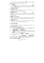
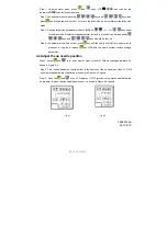
3.1.3
Soft start setup
:
Press
key, entry into soft start status. If choice soft starts, the icon
is lightened in LCD
areas. Press this key again to exit soft start status, the icon
will off.
3.1.4
Press foot lifting key
:
Press
key, entry into foot lifting status, total four different status, no automatic foot lifting
、
automatic foot lifting after trimming
(
)、
automatic foot lifting if stop during sewing
(
)


