PowerMax JACK2000B Instruction Manual Download Page 15


第 15 页 共 16 页

3.4  Monitor mode 

3.4.1 How to enter monitor mode 

During HMI idle, Press

key, then press

key, entry monitor mode. Use   


 keys and 


keys to switch to watch the parameters. About the monitor parameter, please refer the sheet 4, 

HMI will back to idle if no wheel or no press the key in regulates time.   

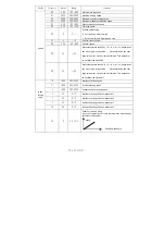
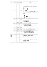
3.4.2 Monitor mode parameter table 

Table 3-3 

monitor mode parameter


Name 

Parameter


unit


comment


1 0 


Counter stitches 

1 1 


Counter trimming   

2 0 

DC Bus Voltage 

2 1 

RPM 

Motor speed 

2 2 

0.01A 

One phase current   

2 3 

degree


Initial angle 

2 4 

degree


Mechanical angle 

2 5 

——


Sampling value of pedal voltage   

2 6 

0.001 

motor/machine head run ratio 

2 7 

hour 

Motor total run time   

Monitor 

status


3 8 

——


Sampling value of potentiometer at 

machine head 

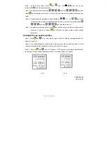
3.5  Wrong warning mode 

If the HMI detects something wrong from controller, it will jump automatically to warning mode, and 

show error code by 8-segment.see 


During wrong warning mode, the user can 

set technician parameter change, administrator parameter and HMI parameter self-change or monitor 

mode. Exit these modes not back to idle but back to wrong warning mode. It will return normal status 

after fixing error and resetting power. 

3.6  Safety switch warning mode 

If HMI test safety switch warning, it will jump automatically to safety switch warning mode, see 

  . During wrong safety switch warning mode, the user can set technician parameter, 

administrator parameter and HMI parameter self-change or monitor mode. Exit these modes not back 

to idle but back to wrong warning mode.

It is reunification 

with the switch input, does not distinguish between safety switch, scissors protection switch


4  Parameter reset to factory settings 

4.1 Restore storage parameter for factory of control 

Summary of Contents for JACK2000B

Page 1: ...ler properly and safely qualified personnel are required Please try to stay away from arc welding equipment in order to avoid electromagnetic interference and malfunction of the controller Keep in roo...

Page 2: ...ack Fig 1 3 Controller Interface Definition If the plug does not go in check the plug and socket matches needle insertion direction or the direction is correct Light socket and presser foot lifter sol...

Page 3: ...eration panel It including pattern sewing mode start end back tacking and foot lifter stop needles and trimming and slow start operation set The operation system automatically power on that HMI will a...

Page 4: ...se end back tacking The current status is displayed on the left of LCD Detailed see 3 1 2 before and after sewing settings instruction 4 Free sewing mode key Every effective pushed the key once the sy...

Page 5: ...switch key It is used to select the folder line function on and off open the clamp function LCD screen below will display folders line status for details see 3 1 9 clamp set 3 System Parameter Setting...

Page 6: ...ngle start back tacking Double start back tacking Four start back tacking Step 2 Stop pressing to confirm then this back tacking mode has been selected Step 3 Change the corresponding parameters A val...

Page 7: ...half needle due to the press time If you keep press that compensation needle always until release button 3 1 9 Clamp function set Use keys Select clamp function is displayed below the LCD screen and t...

Page 8: ...or too much noise and vibration This parameter do not affect the electrical speed 0 A 20 1 20 System decelerate sensitivity D i r e c t d r i v e transmission can be set up to a large value belt trans...

Page 9: ...0 4000 Two segment controls the speed slope mid turning point speed RPM two segment of turning point speed the parameter 30 set to 1 effective Pedal 3 2 800 0 1024 Two segment controls the speed slope...

Page 10: ...ee 5 1 the value is between 35 and 37 3 7 510 0 1024 Pedal step upon running position see 5 1 the value is between 36 and 38 3 8 578 0 1024 Pedal low speed running position upper see5 1 the value is b...

Page 11: ...back pull mode PMX 4 6 100 0 800 Command button to fill half needle time 47 150 0 800 Command button to fill a needle time 5 0 1 1 100 Stitch counting proportion set up 51 1 1 9999 Stitch counting va...

Page 12: ...eration panel 4 Counting down according to stitch number after reaching set value motor should stop automatically recounting should be restart by S4 152 INI CRS or the button A on operation panel 61 0...

Page 13: ...tor mode 3 3 2 Administrator parameter table Table 3 2 Administrator mode parameter Mode Parameter Default Rang Comment 0 2 1 0 1 2 3 Mode selection for trimming sequence 0 According to the parameters...

Page 14: ...B 140 0 359 Clamp end angle 3 1 0 0 1 The automatic test mode selection 0 order stitches 1 order time 3 2 300 0 1000 The safety SW alarm confirm time ms the same way does not distinguish between direc...

Page 15: ...If the HMI detects something wrong from controller it will jump automatically to warning mode and show error code by 8 segment see During wrong warning mode the user can set technician parameter chan...

Page 16: ...p 4 the parameter confirms correct press key until the red light of HMI are bright or buzz produces a long loud release key HMI and the whole system restore storage parameter 4 2 Adjust the up needle...

Reviews: