background image

18

POSITION OF COLLARS

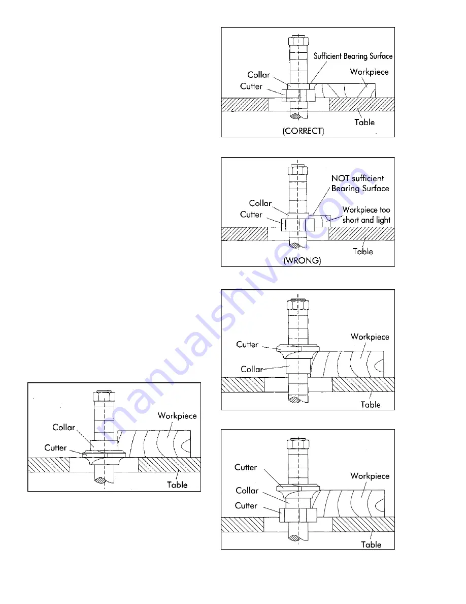
When shaping with collars, the collar must have suffi-
cient bearing surface, as shown in Figure 35.  Also
the work must be fairly heavy relative to the cut being
made.  Under no circumstances should a short, light
workpiece be shaped against the collars, as shown in
Figure 36.

The collars may be used in any of the following posi-
tions:  above, below, or between the cutters.

1.

When the collar is used below the cutter, as shown

in Figure 37, the progress of the cut can be seen
throughout the operation.  However, any accidental lift-
ing of the work will gouge the wood and ruin the
workpiece.

2.

When the collar is used above the cutter, as shown

in Figure  38, the cut can not be seen, but this method
offers an advantage in that the cut is not affected by
slight variations in the thickness of the stock.  Also,
accidental lifting of the workpiece will not gouge the
workpiece; simply repeat the operation to correct the
mistake.

3.

Using the collar between two cutters has the

advantages and disadvantages of the first two proce-
dures, and is frequently used where both edges of the
work are to be molded.  See Figure 39.

NOTE:  It is advisable to place the cutter as low as
possible on the spindle to reduce spindle deflection
and ensure the best possible finish.  Also make sure
that the contacting surfaces of the cutter are smooth,
sharp, clean and without dents.

FIGURE 35

FIGURE 36

FIGURE 37

FIGURE 39

FIGURE 38

Summary of Contents for TS29

Page 1: ...Instruction Manual Parts List M 0460270 800 274 6848 www wmhtoolgroup com SPINDLE SHAPER Model TS29 ...

Page 2: ...O PERSONS OR PROPERTY OR FOR INCIDENTAL CONTINGENT SPECIAL OR CONSEQUENTIALDAM AGES ARISING FROM THE USE OF OUR PRODUCTS SOME STATES DO NOTALLOW THE EXCLUSION OR LIMITATION OF INCIDENTAL OR CONSEQUENTIALDAMAGES SO THEABOVE LIMITATION OR EXCLU SION MAY NOT APPLY TO YOU To take advantage of this warranty the product or part must be returned for examination postage prepaid to an Authorized Repair Sta...

Page 3: ...justments Control Panel Instructions 14 Speed Change 15 Spindle Lock 15 Spindle Vertical Travel 16 Spindle Tilting 16 FenceAdjustment 16 Sliding TableAdjustment 17 Operation 18 Position of Collars 18 Copying Machining with a Jig 19 Feeding Stock 19 Maintenance 20 Trouble Shooting 21 22 Parts Lists Exploded Views Fence Assembly 23 25 SpindleAssembly 26 27 Cabinet Assembly 28 29 Sliding Table Assemb...

Page 4: ...ertain the work area is well lighted and that a proper exhaust system is used to minimize dust Powermatic recommends the use of anti skid floor strips on the floor area where the operator normally stands and that each machine s work area be marked off Provide adequate work space around the machine Operator position Maintain a balanced stance and keep your body under control at all times Do not ove...

Page 5: ...ck stock out of the cutter once the cut has been started Instead pull the stock straight back away from cutter and begin the cut again See Figure 2 Make sure the spindle and the draw bar are tightened on the arbor Safety lock washer Never operate the shaper without the safety locking keyed washer located immediately under the spindle nut See Figure 3 This prevents the nut from coming loose when th...

Page 6: ...om these exposures varies depending on how often you do this type of work To reduce your exposure to these chemicals work in a well ventilated area and work with approved safety equipment such as those dust masks that are specifically designed to filter out microscopic particles Familiarize yourself with the following safety notices used in this manual CAUTION This means that if precautions are no...

Page 7: ...7 SAFETY Familiarize yourself with the location and content of these safety decals on your shaper FIGURE 4 WARNING DO NOT ENGAGE SPINDLE LOCK WHILE MACHINE IS RUNNING 6293077 ...

Page 8: ...7 Spindle speed 3000 4000 6000 8000 10000 Spindles interchangeable 1 1 4 x 6 1 x 6 3 4 x 3 1 4 and 1 2 collet chuck with 1 4 bushing Table inserts three 2 1 2 I D 5 1 2 I D Oval slotted Dust outlet two 5 Net weight 1183 lbs SPECIFICATIONS Model TS29 Spindle Shaper NOTE The above specifications were current at the time this manual was published but because of our policy of continuous improvement Po...

Page 9: ...the bolts securing the machine to the skid 3 The shaper can be lifted by a crane with hoist Figure 6 or by a forklift Figure 7 either of which should be capable of lifting one ton Remove the skid from under the shaper 4 The shaper should be mounted to a solid level foundation preferably a concrete floor With machine in position check table surface left to right and front to back with a machinist s...

Page 10: ...e 8 2 Remove clear plastic insulator C that covers the terminals See Figure 9 3 Insert power line through opening D of terminal strip box shown in Figure 8 4 Connect the three power lines to terminals L1 L2 and L3 as shown at E Figure 10 Also connect the green ground wire to terminal F 5 Reassemble the clear plastic insulator C and the terminal strip cover B CAUTION Make sure the incoming power ma...

Page 11: ... See Figure 12 Remove the two lock nuts and the special bevel washer from the other end of the draw bar B 5 Carefully insert the draw bar B and spindle A down through the shaft as shown in Figure 12 Make sure the tang C on the spindle is engaged with the notch D and thread spindle nut E onto threads F 6 Engage spindle lock refer to Spindle Lock on page 16 7 Use the supplied spanner wrench G to tig...

Page 12: ...C are spring loaded and can be repositioned by pulling out the handle and rotating it on the nut 3 Mount the cover plate K using the two locking knobs and flat washers shown in Figure 16 GUARD ASSEMBLY The guard assembly can be mounted in various con figurations depending upon the type of work being done Figure 16 shows one such configuration 1 Mount the spring guard F hold down G and clear plasti...

Page 13: ...nted as shown and can be ad justed by loosening the screws J MITRE FENCE 1 Slide the mitre fence A on to the two square nuts B that are attached to the threaded part of the locking levers C See Figure 21 2 To slide mitre fence A to the left or right loosen locking levers C slide fence A to the desired posi tion and tighten locking levers C To change the angle of the fence loosen locking handle D A...

Page 14: ...hine push the mushroom shaped stop button E or turn the start stop switch B to the left CAUTION Do not use the forward reverse switch to stop the machine or damage to the electrical controls will occur WARNING Open the electrical cabinet door only while the power is disconnected or it may result in electrical shock SPEED CHANGE Your machine is supplied with a 5 step motor pulley and a 5 step spind...

Page 15: ...sion To obtain best tension turn the two nuts E F Figure 27 Proper belt tension is achieved when the belt midway between the pulleys can be deflected using moderate finger pressure SPINDLE LOCK The spindle lock will assist you in replacing the spindle or installing and removing cutters NOTE The spindle lock can be engaged only when the machine has stopped completely Open rear cabinet door and rota...

Page 16: ...the required positions and tighten locking levers CAUTION The aluminum fence halves should be adjusted inward so that the opening at the spindle is just enough to clear the cutter 2 The right fence half infeed can be moved inde pendently in or out depending on the type of shaping operation that is being performed See Figure 30 To move the right fence half in or out loosen the locking knob A and tu...

Page 17: ...ys be used when the work permits Almost all straight work can be done with the fence 1 For normal work where a portion of the original edge of the stock is not touched by the cutter both the infeed and outfeed fences are in a straight line as shown in Figure 32 2 When the shaping operation removes the entire edge of the stock e g in jointing or making a full bead the shaped edge will not be suppor...

Page 18: ...e 2 Whenthecollarisusedabovethecutter asshown in Figure 38 the cut can not be seen but this method offers an advantage in that the cut is not affected by slight variations in the thickness of the stock Also accidental lifting of the workpiece will not gouge the workpiece simply repeat the operation to correct the mistake 3 Using the collar between two cutters has the advantages and disadvantages o...

Page 19: ...hav ings and dust This will increase machine performance and extend its life Clean the spindle with compressed air Do not get oil on the pulleys and belts If they are dirty use paper or a soft rag to clean and dry them Never place the v belt under excessive strain as this can overload the motor and damage the bearings spindle or belt The table surface must be kept clean and free of rust for best r...

Page 20: ...g the grease gun A supplied See Figure 41 Two grease fittings one of which B is shown are supplied on the spindle housing for this purpose The other grease fitting is directly opposite fitting B Before lubricating clean grease fittings B thoroughly and then lubricate the spindle bearings with two pumps of a good quality non hardening grease FIGURE 41 ...

Page 21: ...n with turpentine and steel wool 3 Gum or pitch on table causing erratic 3 Clean table with turpentine and feed steel wool 4 Feeding work in wrong direction 4 Feed work against cutter rotation 5 Stock burns 1 Dull cutter 1 Sharpen by honing on flat side 2 Cutter too deep 2 On hardwoods take light cuts attain full depth of cut with several passes 3 Forcing work 3 Feed slowly and steadily Machine vi...

Page 22: ...ds work 1 Keep pressure firm throughout pass down on table use hold downs make pass slowly and steadily Whenever possible keep cutter under stock 19 2 Vertical lock not engaged 2 Engage spindle lock 18 Cuts not smooth 1 Wrong R P M 1 Use faster speed 2 Feeding too fast 2 Pass stock more slowly 3 Working against grain 3 Work with grain whenever possible 4 Cutting too deep 4 On very deep cuts make s...

Page 23: ... TS29 016 Horizontal Hex Post Long 1 25 TS 1502021 Socket Head Cap Screw M5 x 10 2 26 TS29 017 Cam Washer 2 27 TS 1502061 Socket Head Cap Screw M5 x 25 2 28 TS29 018 Guard Support Bracket 1 29 TS 1503051 Socket Head Cap Screw M6 x 20 6 30 TS29 019 Fence Cover Plate 1 31 TS 1540041 Hex Nut M6 2 32 TS29 020 Fence Body Casting 1 33 TS29 021 Beveled Flat Washer M14 2 34 TS29 022 Lock Handle 2 35 TS29 ...

Page 24: ...ar 1 71 TS29 044 Collar 1 73 TS29 045 M8 Knob w Stud 2 74 TS29 196 Socket Set Screw M5 x 4 1 75 TS29 046 Bushing 1 76 TS29 047 Vertical Hex Post 1 77 TS29 048 Thumb Screw M8 x 17 8 78 TS 1533042 Pan Head Phillips Machine Screw M5 x 12 4 79 TS 1550031 Flat Washer M5 4 80 TS29 049 Bolt 1 81 TS29 050 Swivel Handle 1 82 TS29 051 Handwheel 1 83 TS29 052 Dust Port 1 84 TS 1523011 Socket Set Screw M6 x 6...

Page 25: ...25 Fence Assembly TS29 Shaper ...

Page 26: ... TS29 061 Interchangeable Spindle 1 1 TS29 062 Interchangeable Spindle 1 1 4 1 9 TS 1502041 Socket Head Cap Screw M5 x 16 4 10 TS29 063 Plate 1 11 BB 6008Z Bearing 6008Z 2 12 TS29 064 Key M6 x 54 1 13 TS29 065 Retaining Ring S40 1 14 TS29 066 Spindle 1 15 TS29 067 Spring Disk 61 5 x 40 5 x 0 7 2 16 BB 6206Z Bearing 6206Z 1 17 TS29 068 Spacer 1 18 TS29 069 Spindle Pulley 1 19 TS29 070 Pulley Nut 1 ...

Page 27: ...27 Spindle Assembly TS29 Shaper ...

Page 28: ...211451 Hex Cap Screw M12 x 45 4 15 TS29 080 Control Panel 1 16 TS 2244102 Pan Head Phillips Machine Screw M4 x 10 3 17 TS 154007 Hex Nut M10 2 18 TS29 081 Fixed Screw 1 19 TS29 082 Spring 1 20 TS29 083 Knob 1 21 TS29 084 Front Cabinet Door 1 22 TS29 085 Front Door Handle 1 23 TS29 086 Latch Assembly 1 24 TS29 087 Hinge Bracket 1 25 TS 1502021 Socket Head Cap Screw M5 x 10 2 26 TS29 088 Handwheel 1...

Page 29: ...29 Cabinet Assembly TS29 Shaper ...

Page 30: ...19 TS29 107 Plunger Pad 1 20 TS29 108 Locking Arm 1 21 TS29 109 Plunger 1 22 TS29 110 Spring 1 23 TS 1524031 Socket Set Screw M8 x 12 1 24 TS29 111 Horizontal Post 1 25 TS 149105 Hex Cap Screw M10 x 35 2 27 TS29 112 Post Clamp 1 28 TS29 113 Vertical Post 1 29 TS29 114 Retaining Ring S25 1 30 TS29 115 Lock Lever M6 2 31 TS29 116 Knob M10 1 33 TS 1550071 Flat Washer M10 1 34 TS29 117 Mitre Gauge Bod...

Page 31: ...31 Sliding Table Assembly TS29 Shaper ...

Page 32: ...Slide 2 3 TS29 131 Rack 1 4 TS29 132 Gear 1 5 TS29 133 Block 1 6 TS29 134 Mount Bracket 1 7 TS29 135 Sensor 1 8 TS29 201 Pan Head Machine Screw 5 32 x 1 1 4 Lg 5 9 TS29 202 Pan Head Machine Screw 5 32 x 1 1 2 Lg 1 10 TS29 136 Terminal 1 11 TS29 203 Hex Nut 5 32 13 12 TS29 137 Spring 1 13 TS29 138 Steel Ball 1 4 1 ...

Page 33: ...33 Speed Indicator TS29 Shaper ...

Page 34: ...No Part No Description Quantity 1 TS29 139 Speed Indicator Light 5 2 TS29 140 Stop Button 1 3 TS29 141 Start Switch 1 4 TS29 142 Forward Reverse Switch 1 5 TS29 143 Transformer 1 6 TS29 144 Control Box 1 7 TS29 145 Magnetic Starter w Overload Relay 1 ...

Page 35: ...35 Electrical Components TS29 Shaper ...

Page 36: ... Top Trunnion L H 1 23 TS 1491081 Hex Cap Screw M10 x 50 1 24 TS29 157 Spacer 1 25 TS29 158 Bottom Trunnion L H 1 26 TS29 159 Trunnion Main Frame 1 27 TS 1491031 Hex Cap Screw M10 x 25 6 28 TS29 160 Spring Hook 1 29 TS 154010 Hex Nut M16 1 30 TS29 161 Quill Housing 1 31 TS 2360121 Flat Washer M12 5 32 TS 2211451 Hex Head Bolt M12 x 45 4 33 TS29 162 Raising Gear 1 34 TS29 163 Base Plate 1 35 TS29 1...

Page 37: ...7 TS 1550061 Flat Washer M8 3 68 TS29 183 Inner Trunnion R H 1 69 TS29 184 Locking Post 1 70 TS29 185 Locking Pin 1 71 TS29 186 Spring 1 72 TS29 187 Spring Retainer 1 73 TS 1523071 Socket Set Screw M6 x 25 1 74 TS29 188 Lock Knob 1 75 TS 1490071 Hex Cap Screw M8 x 40 3 76 TS29 189 Sleeve 1 77 TS29 190 Handle R H 1 78 TS 1502051 Socket Head Cap Screw M5 x 20 8 79 TS29 191 Tilt Shaft End Plate 1 80 ...

Page 38: ...38 Quill Assembly TS29 Shaper ...

Page 39: ...30 a m and 6 00 p m CST Monday through Friday Having the Model Number and Serial Number of your machine available when you call will allow us to serve you quickly and accurately Locating the stock number of the part s required from your parts manual will also expedite your order Phone No 800 274 6848 Website www powermatic com ...

Page 40: ...C WMH TOOLGROUP 2420 Vantage Drive Elgin IL 60123 Phone 800 274 6848 Website www wmhtoolgroup com POWERMATIC ALL RIGHTS RESERVED 08 02 ...

Reviews: