background image


17

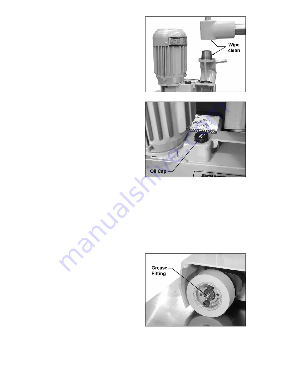
The mating parts of the arm cone and swivel 
cone should be kept clean. See Figure 21. 
When disassembling any of the cones from the 
stock feeder, wipe off both mating parts with a 
clean rag before re-assembling. NOTE: These 
cones are subject to high torques and it may be 
necessary to periodically re-tighten the lock 
handles until the cone surfaces become 
securely seated. 


Lubrication 

Gearbox 

The Stock Feeder is shipped with oil installed in 
the gearbox. Occasionally check the oil level 
and add oil if necessary. The oil level should be 
approximately 1-1/2” deep; that is, about 1” from 
the rim of the hole. Completely drain and refill 
the oil every 1,000 working hours, or every 6 
months, with a good quality gear oil.  

To change the oil: 

1.  Loosen the screw (A, Figure 5) which holds 

the feeder body to the horizontal arm. 

2.  Carefully remove the feeder body from the 

horizontal arm. 

3.  Unscrew and remove the oil cap (identified 

in Figure 22) and turn the feeder body 
upside down to completely drain the oil. 
(NOTE: Always dispose of used oil 
properly.) 

4.  Turn feeder body right side up, and pour 

new oil into the fill hole, until it is about 1” 
from the rim. 

5.  Re-install the oil cap (Figure 22). 


Rollers 

Each of the three rollers has a grease fitting 
(Figure 23) located in the hub center. Use a 
grease gun to insert a good quality, all-purpose 
grease into these fittings every 200 working 
hours, or every 30 days. 


Figure 21 


Figure 22 


Figure 23 

Summary of Contents for PF3-JR

Page 1: ...ions and Parts Manual 3 Roll Powered Stock Feeder Model PF3 JR WMH TOOL GROUP Inc 2420 Vantage Drive Elgin Illinois 60123 Part No M 1790818 Ph 800 274 6848 Revision B 7 08 www powermatic com Copyright 2008 WMH Tool Group ...

Page 2: ...or examination postage prepaid to a location designated by us For the name of the location nearest you please call 1 800 274 6848 You must provide proof of initial purchase date and an explanation of the complaint must accompany the merchandise If our inspection discloses a defect we will repair or replace the product or refund the purchase price at our option We will return the repaired product o...

Page 3: ...2 Edgewise Stock Feeder Position 12 Speed Selection 13 Operating Controls 14 Operation 14 General Operating Instructions 14 When Used with a Shaper 15 When Used with a Table Saw 16 When Used with a Jointer 16 Roller Removal Replacement 16 Maintenance 16 Lubrication 17 Troubleshooting 19 Replacement Parts 19 Parts List PF3 JR Stand Assembly 20 PF3 JR Stand Assembly 21 Parts List PF3 JR Stock Feeder...

Page 4: ... and chromium from chemically treated lumber Your risk of exposure varies depending on how often you do this type of work To reduce your exposure to these chemicals work in a well ventilated area and work with approved safety equipment such as face or dust masks that are specifically designed to filter out microscopic particles 10 Do not operate this machine while tired or under the influence of d...

Page 5: ...uctions for lubricating and changing accessories 27 Turn off the stock feeder before cleaning Use a brush or compressed air to remove chips or debris do not use your hands 28 Do not stand on the machine Serious injury could occur if the machine tips over 29 Never leave the machine running unattended Turn the power off and do not leave the machine until it comes to a complete stop 30 Remove loose i...

Page 6: ...ing for all types of materials The stand is fully adjustable with universal joints and heavy locking mechanisms secure the feeder in horizontal vertical or angled positions The roller system is maintenance friendly allowing you to replace a single roller if necessary instead of a complete set Specifications Model Number PF3 JR Stock Number 1790818 Approx Length with arm fully extended and handle i...

Page 7: ...7 Features ...

Page 8: ...parts list to make sure all parts are intact Missing parts if any should be reported to your distributor Read the instruction manual thoroughly for assembly maintenance and safety instructions Contents of the Shipping Container 1 Stock Feeder 1 Stand Assembly 2 Handles 1 26 Tooth Gear 1 24 Tooth Gear 1 Boring Template 1 Owner s Manual 1 Warranty Card Read and understand the entire contents of this...

Page 9: ...r during installation 1 Determine the mounting location for the stand Keep in mind the overall length of the horizontal arm on the stand 27 1 2 so that there will be enough adjustment when the Stock Feeder is mounted IMPORTANT Locate the stand so that you will not drill through any ribs or supports beneath the table surface 2 Use the provided boring template to find the centerline spacing for the ...

Page 10: ...gure 3 9 Attach a handle Figure 4 to each elevating handle by screwing the threads of the handle into the hole on the elevating handle 10 The handle Figure 4 should be adjusted so that it can move freely Loosen the hex nut with a 14mm 9 16 wrench and turn the socket head cap screw with a 5mm hex wrench until the handle is just loose enough to turn freely Then tighten the hex nut against the elevat...

Page 11: ...green with or without yellow stripes is the equipment grounding conductor If repair or replacement of the electric cord or plug is necessary do not connect the equipment grounding conductor to a live terminal Check with a qualified electrician or service personnel if the grounding instructions are not completely understood or if in doubt as to whether the tool is properly grounded Use only three w...

Page 12: ... 9 When adjustment is complete re tighten lock handle C Figure 9 The vertical column and horizontal arm have stop screws E Figure 9 which prevent them from being moved too far To rotate the entire stand assembly loosen the lock handle F Figure 9 and push the assembly into desired position Tighten lock handle before operating the stock feeder To rotate the stock feeder alone loosen lock handle G Fi...

Page 13: ...per position of the gears Unplug the stock feeder from power source before changing gears To change the position of the gears 1 Unscrew the knob Figure 11 and pull off the back cover to expose the gear system shown in Figure 12 2 Remove hex nuts and flat washers A Figure 12 with a 14mm wrench 3 Figure 13 shows the relationship of gear position to create each of the four speeds A similiar chart is ...

Page 14: ... Keep hands away from rollers during operation Failure to comply may cause injury General Operating Instructions 1 Make sure all lock handles are tight before operating the Stock Feeder 2 The Stock Feeder should be used in conjunction with a fence on your auxiliary machine 3 The rollers must grip the offcut as well as the part of the workpiece still being fed 4 On some machines such as a shaper th...

Page 15: ...be inclined slightly towards the work table in the direction of feed to ensure the workpiece remains forced down against the table In other words the outfeed roller should be approximately 3 16 closer to the work table than the infeed roller See Figure 17 4 When the Stock Feeder is in the edgewise position or angled for a beveled workpiece the axis of the cutter should be between the outfeed rolle...

Page 16: ...d is angled slightly toward the fence by approximately 3 16 5mm that is the outfeed roller should be slightly closer to the fence than the infeed roller See Figure 19 Roller Removal Replacement If more space is needed between rollers for example when feeding a curved workpiece the center roller can be removed from the Stock Feeder To remove the roller loosen and remove the two socket head cap scre...

Page 17: ...pletely drain and refill the oil every 1 000 working hours or every 6 months with a good quality gear oil To change the oil 1 Loosen the screw A Figure 5 which holds the feeder body to the horizontal arm 2 Carefully remove the feeder body from the horizontal arm 3 Unscrew and remove the oil cap identified in Figure 22 and turn the feeder body upside down to completely drain the oil NOTE Always dis...

Page 18: ...th good quality all purpose grease every 3 months or more frequently if needed Lead Screws Occasionally apply a light coat of grease to the lead screw of the vertical column and to the lead screw of the horizontal arm See Figure 25 Figure 24 Figure 25 ...

Page 19: ...ot sufficient machine has low power Low current from electrical supply Contact a qualified electrician Workpiece jams while feeding it beneath rollers Rollers too low Raise feeder Workpiece slips while passing under rollers Rollers too high no traction Lower feeder Rollers slip on workpiece Grease or debris on rollers Clean rollers Replacement Parts Replacement parts are listed on the following pa...

Page 20: ...2 TS 2310162 Hex Nut M16x1 5P 1 13 PF3JR 113 Lock Handle 1 14 TS 1550071 Flat Washer M10 1 15 TS 1491081 Hex Cap Screw M10x50 1 16 PF3JR 116 Handle 2 17 PF3JR 117 Vertical Column 1 18 PF3JR 118 Horizontal Arm 1 19 PF3JR 119 Elevating Screw 1 20 PF3JR 120 Horizontal Screw 1 21 PF3JR 121 Column Cap 1 22 TS 1524031 Socket Set Screw M8x12 3 23 PF3JR 123A Elevating Handle 2 24 PF3JR 124 Pin 4x30 mm 2 2...

Page 21: ...21 PF3 JR Stand Assembly ...

Page 22: ...k Washer M8 3 23 TS 1540061 Hex Nut M8 3 24 PF3JR 224 Frame 1 25 PF3JR 225 Bushing 1 26 PF3JR 226 Sprocket 2 27 PF3JR 227 Sprocket 2 28 PF3JR 228 Bushing 1 29 PF3JR 229 Chain 30S 30S 1 30 PF3JR 230 Chain 22S 22S 1 31 PF3JR 231 Worm Gear Shaft 1 32 TS 1550071 Flat Washer M10 1 33 TS 1540071 Hex Nut M10 1 34 PF3JR 234 Oil Seal 1 35 PF3JR 235 Bushing 1 36 PF3JR 236 Worm Gear Cover 1 37 PF3JR 237 Oil ...

Page 23: ...23 PF3 JR Stock Feeder ...

Page 24: ...24 PF3 JR Electrical Connections ...

Page 25: ...25 Boring Template SCALE 1 1 Cut out and tape into place on mounting surface ...

Page 26: ...26 NOTES ...

Page 27: ...27 ...

Page 28: ...28 WMH Tool Group Inc 2420 Vantage Drive Elgin Illinois 60124 Phone 800 274 6848 www powermatic com www wmhtoolgroup com ...

Reviews: