background image


16 

8.1.2

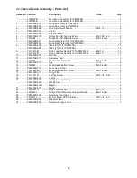
  Rail Assembly – Parts List 

Index No  Part No 

Description 

Size 

Qty 

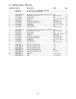
 .................. 2653031B .................. 50" PW Rail Set for PM2000B & PM3000B .............  ........................................  
 .................. 2653039B .................. 30" PW Rail Set for PM2000B .................................  ........................................  


 .................. PM2000B-HK-50 ....... Hardware Kit for 50" Rail Assembly (includes #1 thru 9) ................................ 1 
1 ................ TS-1504041 .............. Socket Head Cap Screw ......................................... M8-1.25P x 20L ............ 2 
2 ................ TS-1551061 .............. Lock Washer ............................................................ M8 ............................... 16 
3 ................ TS-1550061 .............. Flat Washer ............................................................. 8.5 x 16 x 2.0T mm ..... 21 
4 ................ TS-2311081 .............. Hex Nut .................................................................... M8-1.25P .................... 14 
5 ................ TS-1504081 .............. Socket Head Cap Screw ......................................... M8-1.25P x 40L ............ 5 
6 ................ TS-1515051 .............. Socket Head Flat Screw .......................................... M8-1.25P x 40L ............ 9 
7 ................ TS-1550041 .............. Flat Washer ............................................................. 6.3 x 13 x 2.0T mm ....... 8 
8 ................ TS-1551041 .............. Lock Washer ............................................................ M6 ................................. 8 
9 ................ TS-1482041 .............. Hex Cap Screw ........................................................ M6-1.0P x 20L .............. 8 


 .................. PM2000B-HK-30 ....... Hardware Kit for 30" Rail Assembly (includes #1 thru 9) ................................ 1 
1 ................ TS-1504041 .............. Socket Head Cap Screw ......................................... M8-1.25P x 20L ............ 2 
2 ................ TS-1551061 .............. Lock Washer ............................................................ M8 ............................... 10 
3 ................ TS-1550061 .............. Flat Washer ............................................................. 8.5 x 16 x 2.0T mm ..... 12 
4 ................ TS-2311081 .............. Hex Nut .................................................................... M8-1.25P ...................... 8 
5 ................ TS-1504081 .............. Socket Head Cap Screw ......................................... M8-1.25P x 40L ............ 2 
6 ................ TS-1515051 .............. Socket Head Flat Screw .......................................... M8-1.25P x 40L ............ 6 
7 ................ TS-1550041 .............. Flat Washer ............................................................. 6.3 x 13 x 2.0T mm ....... 6 
8 ................ TS-1551041 .............. Lock Washer ............................................................ M6 ................................. 6 
9 ................ TS-1482041 .............. Hex Cap Screw ........................................................ M6-1.0P x 20L .............. 6 


10 .............. PM2000B-610 ........... Back Fence Rail (50” rip) ......................................... 72” L .............................. 1 
 .................. PM2000B-610S ......... Back Fence Rail (30” rip) ......................................... 52” L .............................. 1 
11 .............. PM2000B-611 ........... Front Fence Rail (50” rip)......................................... 72” L .............................. 1 
 .................. PM2000B-611S ......... Front Fence Rail (30” rip)......................................... 52” L .............................. 1 
12 .............. PM2000B-612 ........... Front Fence Guide (50” rip) ..................................... 84” L .............................. 1 
 .................. PM2000B-612S ......... Front Fence Guide (30” rip) ..................................... 64-1/4” L ....................... 1 
13 .............. PM2000B-613 ........... Tube Cap .................................................................  ...................................... 2 
14 .............. PM2000B-614 ........... Scale ........................................................................ 53"L x 3/4"W ................. 1 
 .................. PM2000B-614S ......... Scale ........................................................................ 32"L x 3/4"W ................. 1


Summary of Contents for Accu-Fence

Page 1: ...d Parts Manual Accu Fence and Rail System For PM2000B PM3000B Table Saws Powermatic 427 New Sanford Road LaVergne Tennessee 37086 Part No M 2195079B Ph 800 274 6848 Edition 2 10 2018 www powermatic com Copyright 2017 Powermatic ...

Page 2: ...s and adjusting wrenches are removed from the machine before turning it on 14 Keep safety guards in place at all times when the machine is in use If removed for maintenance purposes use extreme caution and replace the guards immediately 15 Check the alignment of the riving knife fence and miter slot to the blade A caution decal is installed on each guard to remind the operator of the dangers of im...

Page 3: ...f material from the table that can strike the operator Kickback can also result in the operator s hands being pulled into the blade Kickback Prevention Tips to avoid the most common causes of kickback Make sure the riving knife is always aligned with the blade A workpiece can bind or stop the flow of the cut if the riving knife is misaligned and result in kickback Use a riving knife during every c...

Page 4: ...allation safety precautions general operating procedures maintenance instructions and parts breakdown Your fence has been designed and constructed to provide consistent long term operation if used in accordance with the instructions set forth in this document This manual is not intended to be an exhaustive guide to table saw operational methods use of jigs or after market accessories choice of sto...

Page 5: ...3 Installing back rail 8 6 4 Installing wood extension table optional accessory 9 6 5 Installing guide tube 10 6 6 Mounting Accu Fence 11 6 7 Side plate replacement 12 7 0 Rail installation on a non Powermatic Saw 13 7 1 Tools required for assembly 13 7 2 Installing front rail 13 7 3 Installing back rail 14 8 0 Replacement parts 15 8 1 1 Rail Assembly Exploded View 15 8 1 2 Rail Assembly Parts Lis...

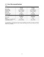
Page 6: ...olyethylene Cross bar length 16 in 407 mm 16 in 407 mm Rail Sets 30 in Rip set 50 in Rip set Stock number 2653039B 2653031B Material Steel Steel Actual length front and back rails 52 in 132 cm 72 in 183 cm Actual length guide tube 64 1 4 in 163 cm 84 in 213 cm The specifications in this manual were current at time of publication but because of our policy of continuous improvement Powermatic reserv...

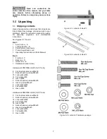
Page 7: ... card 1 Operating Instructions and Parts Manual Box 2 1 Front rail C 1 Back rail D 1 Guide tube E 1 Hardware kit see below Hardware kit PM2000B HK 30 for 30 rails 6 Flat head socket screw M8x40 2 Socket head cap screw M8x40 10 Lock washer M8 12 Flat washer M8 8 Hex nut M8 2 Socket head cap screw M8x20 6 Hex cap screw M6x20 6 Lock washer M6 6 Flat washer M6 6 Hex nut M6 Hardware kit PM2000B HK 50 f...

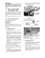
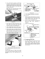
Page 8: ...aw s extension wings are not pre drilled at the factory so use of the first hole on the rail is optional Also rails are designed to be shifted to the right to accommodate attachments such as a sliding table not included 3 Lightly secure front rail to saw table with four M8x40 flat head screws with washers and hex nuts Figure 6 2 Finger tighten only The front rail must be parallel to table top in o...

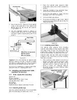
Page 9: ...t require legs proceed to sect 6 4 3 1 Place the optional wood extension table upside down Use a mat or cloth to protect the surface 2 Install leg brackets to the pre drilled holes using screws provided with the legs 3 Press both ball detents A Figure 6 6 and swing leg until it clicks into position 4 Turn wood table right side up 5 The levelers at bottom of legs can be rotated to help level wood t...

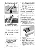
Page 10: ...s first Drill 9mm or 11 32 holes into front edge and back edge of table using holes in the rails as your guide Figure 6 9 6 4 4 Securing wood table to front rail See Figure 6 10 Insert flat head screws A Figure 6 10 through front rail and wood extension table and secure with washers and hex nuts Finger tighten only at this time Figure 6 10 6 4 5 Securing wood table to back rail See Figure 6 11 1 I...

Page 11: ...de plate height 1 Figure 6 14 shows a fence where misalignment of side plates has occurred the side plates are in contact with front edge of saw table Figure 6 14 2 Turn Accu Fence upside down and with a rubber mallet or hammer and block of wood gently tap the side plates to create a height greater than 1 32 from table top Note Do not use a steel faced hammer directly on the side plates as this wi...

Page 12: ...t cursor F Figure 6 16 to read the distance just measured and tighten cursor assembly to fence 6 Take a test cut and confirm that the adjustment is correct Note Slots in cursor should allow enough adjustment travel If cursor lacks enough travel to give correct measurement loosen guide tube and adjust as needed If you still cannot achieve correct measurement loosen front rail and adjust as needed I...

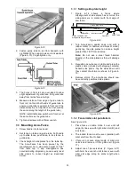
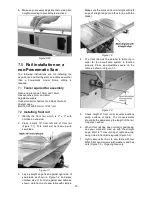
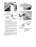
Page 13: ...sh against right side of saw blade as shown in Figure 7 2 and place notched side of front rail against saw table as shown Hold front rail to saw table with clamps Make sure the mark on front rail aligns with left edge of straight edge and thus in line with the blade Figure 7 2 4 The front rail must be parallel to table top in order for the Accu Fence system to function properly Place an adjustable...

Page 14: ... Figure 7 6 Hold back rail to saw with clamps 3 Drill 9mm or 11 32 holes into lip of saw table using holes in back rail as guide Figure 7 7 4 Insert socket head cap screws with washers through back rail and saw table and secure with washers and hex nuts See Figure 7 8 Finger tighten only at this time The rest of the installation is the same as with a Powermatic table saw Refer back to sect 6 4 to ...

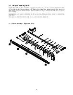
Page 15: ...usiness hours www powermatic com Having the Model Number and Serial Number of your machine available when you call will allow us to serve you quickly and accurately Non proprietary parts such as fasteners can be found at local hardware stores or may be ordered from Powermatic Some parts are shown for reference only and may not be available individually 8 1 1 Rail Assembly Exploded View ...

Page 16: ... HK 30 Hardware Kit for 30 Rail Assembly includes 1 thru 9 1 1 TS 1504041 Socket Head Cap Screw M8 1 25P x 20L 2 2 TS 1551061 Lock Washer M8 10 3 TS 1550061 Flat Washer 8 5 x 16 x 2 0T mm 12 4 TS 2311081 Hex Nut M8 1 25P 8 5 TS 1504081 Socket Head Cap Screw M8 1 25P x 40L 2 6 TS 1515051 Socket Head Flat Screw M8 1 25P x 40L 6 7 TS 1550041 Flat Washer 6 3 x 13 x 2 0T mm 6 8 TS 1551041 Lock Washer M...

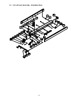
Page 17: ...17 8 2 1 Accu Fence Assembly Exploded View ...

Page 18: ... Nylon Lock Hex Nut q ty 10 for PM2000B M6 1 0 10 TS 1541021 Nylon Lock Hex Nut q ty 12 for PM3000B M6 1 0 12 10 PM2000B 510 End Cap 1 11 PM2000B 511 Fluoroway Pad 3 12 F010946 Socket Head Flat Screw M4 0 7 x 8L 2 13 PM2000B 513 Plug H 13 2 14 F009884 Socket Head Button Screw M5 0 8 x 8L 2 15 PM2000B 515 Fence Head Cover 1 16 TS 2246082 Socket Head Button Screw M6 1 0 x 8L 2 17 PM2000B 517 Spring ...

Page 19: ... a product requires further inspection the Technical Service representative will explain and assist with any additional action needed Powermatic has Authorized Service Centers located throughout the United States For the name of an Authorized Service Center in your area call 1 800 274 6846 or use the Service Center Locator on the Powermatic website More Information Powermatic is constantly adding ...

Page 20: ...20 427 New Sanford Road LaVergne Tennessee 37086 Phone 800 274 6848 www powermatic com ...

Reviews: