


26
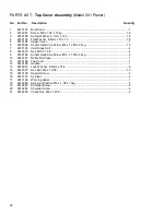
PARTS LIST: Top Cover Assembly (Model 201 Planer)
No. Part No.
Description
Quantity
1 6012181
Dust
Hood............................................................................................................1
2
6012091
Screw, M6 x 1.0P x 10Lg ................................................................................... 18
3
6012182
Spring Washer, 6.1mm x 12.3 ........................................................................... 18
4
6012183
Flat Washer, 6.6mm x 13 x 1T........................................................................... 18
5 6012184
Upper
Cover ........................................................................................................1
6
6012066
Socket Head Cap Screw, M8 x 1.25P x 25Lg..................................................... 10
7
6012185
Cast Hinge Half ...................................................................................................4
8
6012079
Nut, M10 x 1.5P...................................................................................................4
9
6012186
Socket Head Cap Screw, M10 x 1.5P x 60Lg.......................................................2
10 6012187 Deflection
Plate ...................................................................................................1
11 6012188 Top
Cover............................................................................................................1
12 6012189 Handle .................................................................................................................1
13
6012067
Lock Washer, 8.2mm x 15.4 ................................................................................6
14
6012097
Hex Nut, M8 x 1.25P.......................................................................................... 10
15 6012190 Special
Screw......................................................................................................2
16 6012191 Cylinder ...............................................................................................................2
17 6012192 Warning
Label .....................................................................................................1
18
6012282
Screw w/ Washer, M6 x 1.0P x 10Lg....................................................................4
19 6012283 Shoulder
Screw ...................................................................................................2
20 6012284 Shoulder
Screw ...................................................................................................2
21
6012285
Check Nut, M8 x 1.25P ........................................................................................2
Summary of Contents for 201
Page 1: ...22 PLANER Model 201 Instruction Manual Parts List M 0460224 800 274 6848 www powermatic com ...
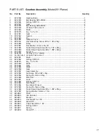
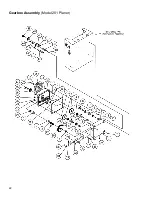
Page 22: ...22 Gearbox Assembly Model 201 Planer ...
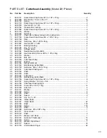
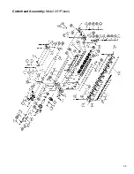
Page 25: ...25 Cutterhead Assembly Model 201 Planer ...
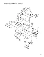
Page 27: ...27 Top Cover Assembly Model 201 Planer ...
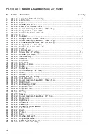
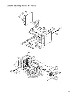
Page 29: ...29 Column Assembly Model 201 Planer ...
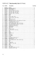
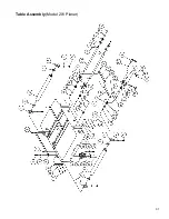
Page 31: ...31 Table Assembly Model 201 Planer ...
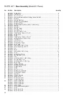
Page 34: ...34 Base Assembly Model 201 Planer ...
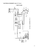
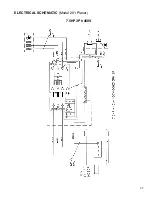
Page 35: ...35 ELECTRICAL SCHEMATIC Model 201 Planer 7 5HP 1Ph 230V ...
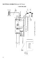
Page 36: ...36 ELECTRICAL SCHEMATIC Model 201 Planer 7 5HP 3Ph 230V ...
Page 37: ...37 ELECTRICAL SCHEMATIC Model 201 Planer 7 5HP 3Ph 460V ...
Page 38: ...38 ...