background image


10

NOTE: Insufficient belt tension will cause 
slippage of conveyor belt on drive roller during 
sanding operation. The conveyor belt is too 
loose if it can be stopped by hand pressure 
applied directly to top of moving conveyor belt. 
Excessive belt tension can result in bent rollers, 
bent brackets, and/or premature wearing of 
bushings or conveyor belt. 

3.  Reinstall left side cover when tensioning is 

complete. 


Figure 11 

7.2.2

  Tracking adjustment  

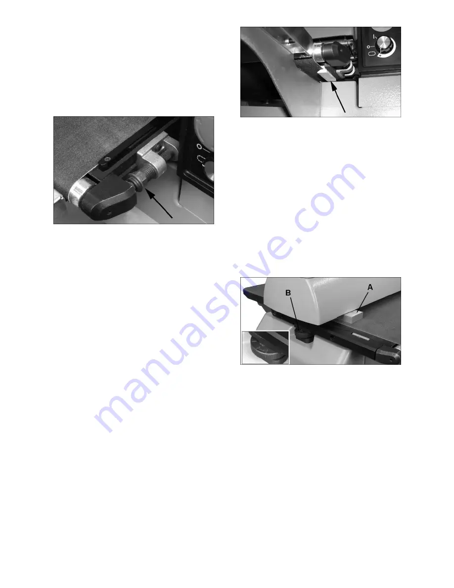
A belt tracks correctly when it moves centrally on the 
conveyor rollers without drifting to either side. 
Tracking adjustments are made while conveyor belt 
is running.  

1.  Make sure proper belt tension has been 

achieved (see

 7.2.1 Tension adjustment

). 

2.  Turn on conveyor and set to maximum speed. 

Watch for a tendency of conveyor belt to drift to 
one side of conveyor. If it drifts, tighten or 
loosen take-up screw nut on 

right side

 of 

conveyor (Figure 11).  

Note:

 Adjust take-up screw nut only 1/4 turn at 

a time. Then allow time for belt to react to 
adjustments before proceeding further.  

Try to avoid over adjustments, as this may 
affect belt tension. If tension is affected, if may 
become necessary to remove left side cover 
and use both take-up screw nuts to accomplish 
tensioning and tracking. 

7.2.3

  Trackers  

The sander comes equipped with “Trackers”, 
ceramic guides that reduce the amount of 
adjustments needed to keep the conveyor belt 
tracked (centered) on the conveyor bed. See Figure 
12. These guides have a magnetic backing to keep 
them in place. If a Tracker wears through, it can be 
reversed by turning it over. See 

sect. 11.0 Tracker 

Kit

 for more information about re-setting trackers. 


Figure 12 

7.4

  Inspecting drum alignment 

The sanding drum must be parallel to conveyor bed 
for proper machine operation. The sanding drum 
comes pre-aligned from the manufacturer. If a 
problem with drum alignment should occur, follow 
the instructions below. 

First, inspect the alignment with a gauge of some 
kind. The following procedure uses a steel block as 
a gauge.  

1.  Unplug sander from power source. 

2.  Open dust cover and remove abrasive strip 

from drum.  

3.  Insert gauge (A, Figure 13) between drum and 

conveyor bed at outboard side of drum. 


Figure 13 

4.  With dust cover open, lower sanding drum while 

slowly rotating drum by hand, until drum lightly 
contacts gauge. 

5.  Remove gauge and place under drum at 

inboard side.  

6.  If drum does not contact gauge equally on both 

ends of drum, alignment is needed. 

To align drum: 

7.  Turn adjustment dial (B, Figure 13) to raise or 

lower outboard end of table. Follow directional 
marks on dial (

+

 to raise). 

Summary of Contents for 1792244

Page 1: ...ng Instructions and Parts Manual Drum Sander Model PM2244 Powermatic 427 New Sanford Road LaVergne Tennessee 37086 Part No M 1792244 Ph 800 274 6848 Edition 1 08 2015 www powermatic com Copyright 2015 Powermatic ...

Page 2: ...reated lumber Your risk of exposure varies depending on how often you do this type of work To reduce your exposure to these chemicals work in a well ventilated area and work with approved safety equipment such as face or dust masks that are specifically designed to filter out microscopic particles 11 Do not operate this machine while tired or under the influence of drugs alcohol or any medication ...

Page 3: ...nment Don t use power tools in damp or wet location or expose them to rain Keep work area well lighted 36 Tighten the caster lock knobs before operating the sander Familiarize yourself with the following safety notices used in this manual This means that if precautions are not heeded it may result in minor injury and or possible machine damage This means that if precautions are not heeded it may r...

Page 4: ...ration 12 8 6 Unit conversion 12 8 7 Drum height setting 12 8 8 Emergency stop 13 8 9 Switch safety key 13 8 10 Setting depth of cut 13 8 11 Establishing drum height 13 8 12 Selecting conveyor rate 13 8 13 Maximum performance tips 14 9 0 Maintenance 15 9 1 Cleaning and lubrication 15 9 2 Drum maintenance 15 9 3 Conveyor belt replacement 15 10 0 Optional abrasives 16 10 1 Abrasive dimensions for PM...

Page 5: ...rials Main body cast iron and steel Enclosed cabinet steel Drum extruded aluminum Extension tables steel Conveyor bed cast iron Handwheel cast iron Sanding drum Drum dimensions dia 5 in x 22L 127 x 559 mm Drum speed 1720 RPM Sanding paper installed 80 grit Drum elevation per one rotation of handwheel 2 12 mm Conveyor Conveyor speed infinitely variable within 0 to 10 FPM 0 3 MPM Conveyor bed dimens...

Page 6: ...E 16 Socket hd cap screws M8x20 HP1 16 Lock washers M8 HP2 16 Flat washers M8 HP3 Read and understand all assembly instructions before attempting assembly Sander must be disconnected from power during assembly procedures Failure to comply may cause serious injury 5 2 Tools required for assembly Hex wrenches 4mm 6mm Open end wrench 14mm Straight edge such as straight steel bar or carefully jointed ...

Page 7: ... Figure 3 5 6 Caster lock knobs Screw the caster lock knobs E Figure 2 into the threaded holes on the side of the cabinet Always tighten the caster lock knobs before operating the sander 5 7 Dust Collection Dust collection is mandatory for a safe work environment and extended abrasive life The PM2244 is equipped with a 4 inch dust collection port Secure a 4 inch dust collection hose to the port wi...

Page 8: ...If connected to a circuit protected by fuses use time delay fuse marked D Local codes take precedence over recommendations 6 1 GROUNDING INSTRUCTIONS This machine must be grounded In the event of a malfunction or breakdown grounding provides a path of least resistance for electric current to reduce the risk of electric shock This tool is equipped with an electric cord having an equipment grounding...

Page 9: ...20 240 25 50 50 100 100 200 150 300 AWG 00 06 18 16 16 14 06 10 18 16 14 12 10 12 16 16 14 12 12 16 14 12 Not Recommended Table 1 Extension cord recommendations 7 0 Adjustments Disconnect sander from power source before making adjustments 7 1 Depth scale The depth scale indicates distance between bottom of sanding drum and top of conveyor belt Adjustment is performed by zeroing the scale 1 With an...

Page 10: ...take up screw nuts to accomplish tensioning and tracking 7 2 3 Trackers The sander comes equipped with Trackers ceramic guides that reduce the amount of adjustments needed to keep the conveyor belt tracked centered on the conveyor bed See Figure 12 These guides have a magnetic backing to keep them in place If a Tracker wears through it can be reversed by turning it over See sect 11 0 Tracker Kit f...

Page 11: ...lignment for wider over 22 sanding When sanding narrow stock less than 22 turn dial opposite direction the same amount as the initial wide sanding so that drum is again parallel 7 5 Tension roller adjustment The infeed and outfeed rollers are tensioned to provide downward pressure on the workpiece to prevent slippage on the feed conveyor Tension rollers have been set by the manufacturer but should...

Page 12: ...ill run and ON will illuminate Note If drum motor does not start make sure conveyor speed dial C is set to OFF 5 Load indicator H may illuminate When motor is running without load one bar may illuminate More bars are illuminated as load increases 6 Turn off drum motor switch B ON will go dark Circle J will continue running for 5 seconds while drum slows to a stop Then circle J will stop running Do...

Page 13: ...tacts the stock Drum should still rotate by hand Without changing drum height finish feeding the stock under the sander Start sanding drum and sand the stock at that same position Do not start drum while in contact with stock For sanding with grits coarser than 80 you can lower the drum slightly Always maintain control of stock Through practice you will learn the proper depth of cut considering th...

Page 14: ...there is a significant thickness difference the thinner pieces can slip on the conveyor belt if they do not contact the tension rollers Also note that pieces thicker than 3 4 should be longer than the minimum normally recommended to prevent tipping of the stock 8 13 4 Edge sanding When edge sanding the sander will mimic the opposite edge of the stock which is lying on the conveyor belt Because of ...

Page 15: ...val from the machine under normal circumstances Should maintenance ever become necessary the drum has been designed for easy removal and replacement Remove four socket head screws C Figure 19 Carefully lift out drum with coupling D attached Figure 19 9 3 Conveyor belt replacement 1 Disconnect sander from power 2 Raise drum to highest position 3 Loosen take up screw nuts Figure 11 on both sides of ...

Page 16: ...G qty 3 1792204 PM2244 Precut Abrasive 100G qty 3 1792205 PM2244 Precut Abrasive 120G qty 3 1792206 PM2244 Precut Abrasive 150G qty 3 1792207 PM2244 Precut Abrasive 180G qty 3 1792208 PM2244 Precut Abrasive 220G qty 3 10 1 Abrasive dimensions for PM2244 Use this diagram to cut after market abrasive strips to fit or use a new Powermatic supplied strip as a template Figure 20 ...

Page 17: ...ot wears out 8 Install second tracker opposite the first Use both trackers unless the second one does not fit in conveyor or unless conveyor belt is damaged 9 Turn conveyor table right side up and re position it onto sander Re attach three 3 mounting screws and tighten Caution Be careful not to knock tracker s out of conveyor bed when turning conveyor over Trackers may break if allowed to fall 10 ...

Page 18: ...ishing because of its open pores 12 2 Cleaning abrasive strips Regularly clean the abrasive strip on the drum with commercially available cleaning sticks following the manufacturer s directions When cleaning also brush the stick crumbs from the drum while it is still rotating In some cases heavy loaded areas can be removed with Plexiglas held on edge over the rotating drum Always wear eye protecti...

Page 19: ...s inspected and repaired Motor stalls resulting in blown fuses or tripped circuit Short circuit in motor or loose connections Inspect connections on motor for loose or shorted terminals or worn insulation Low voltage Correct low voltage conditions Incorrect fuse or circuit breaker in power line Install correct fuse or circuit breaker Loud repetitive noise or vibration coming from machine Fasteners...

Page 20: ...20 14 1 1 PM2244 Head Assembly I Exploded View ...

Page 21: ...21 14 1 2 PM2244 Head Assembly II Exploded View ...

Page 22: ...22 14 1 3 PM2244 Head Assembly III Exploded View ...

Page 23: ...2244 124 Phillips Round Head Screw M4 0 7P 25L 4 25 PM2244 125 Compression Spring 4 26 F002631 Flat Washer 4 10 1 0T 6 27 F010384 Socket Set Screw M4 0 7P 4L 4 28 PM2244 128 Tension Roller Bracket 2 29 PM2244 129 Left Tension Roller Suspension Bracket 2 30 PM2244 130 Oilite Bushing 4 31 PM2244 131 Right Tension Roller Suspension Bracket 2 32 PM2244 132 Shoulder Screw 4 33 PM2244 133 Tension Roller...

Page 24: ...t Head Cap Screw M8 1 25P 25L 4 87 PM2244 187 Sanding Motor 1 75HP 115V 60Hz 1 PM2244 187SC Start Capacitor not shown 300MFD 125VAC 1 PM2244 187RC Running Capacitor not shown 50μF 300VAC 1 PM2244 187FC Fan Cover not shown 1 PM2244 187CF Cooling Fan not shown 1 88 PM2244 188 Strain Relief PGA16 14B 1 89 PM2244 189 Motor Cable 12AWG 3C 1 90 JSG96 262 Self Tapping Screw M3 1 06P 10 8 91 PM2244 191 Di...

Page 25: ...4 1128 Gear Motor Plate 1 129 PM2244 1129 Cable Clamp ACC 2 B 1 130 F010955 Flat Head Socket Screw M5 0 8P 10L 4 131 PM2244 1131 Speed Hall Sensor 1 132 PM2244 1132 Speed Hall Sensor Bracket 1 133 F005349 Socket Head Cap Screw M4 0 7P 6L 2 134 F005382 Socket Head Cap Screw M6 1 0P 16L 6 135 F001207 Phillips Pan Head Screw M5 0 8P 20L 3 136 PM2244 1136 Cable Clamp 1 137 PM2244 1137 Cable Protection...

Page 26: ...26 14 2 1 PM2244 Conveyor Bed Assembly Exploded View ...

Page 27: ...8 1 25P 70L 1 18 PM2244 218 Compression Spring 1 19 F005370 Socket Head Cap Screw M5 0 8P 40L 1 20 F002108 Lock Washer M5 3 21 F002640 Flat Washer 8 5 16 2 0T 3 22 PM2244 222 Sleeve 1 23 PM2244 223 Left Driving Roller Holder 1 24 F005352 Socket Head Cap Screw M4 0 7P 12L 2 25 PM2244 225 Conveyor Bed 1 26 PM2244 226 Guide Bar 1 27 PM2244 227 Driving Roller 1 28 PM2244 228 Spring Pin 4 18 1 29 F0054...

Page 28: ...5 F002640 Flat Washer 8 5 16 2 0T 6 6 F002114 Lock Washer M8 6 7 F005403 Socket Head Cap Screw M8 1 25P 20L 6 8 F006242 Hex Cap Bolt 3 8 16NC 2 1 2 L 4 9 F001511 Nylon Insert Lock Nut 3 8 16NC 4 10 PM2244 310 Caster 4 11 PM2000 105 Powermatic Name Plate 1 12 F000105 Phillips Round Head Screw 1 4 20NC 3 8 L 2 13 PM2244 313 Screw Knob 2 14 PM2244 314 Powermatic Stripe Set 1 15 LM000071 Warning Label...

Page 29: ...29 15 0 Electrical Connections PM2244 Drum Sander ...

Page 30: ...f a product requires further inspection the Technical Service representative will explain and assist with any additional action needed Powermatic has Authorized Service Centers located throughout the United States For the name of an Authorized Service Center in your area call 1 800 274 6846 or use the Service Center Locator on the Powermatic website More Information Powermatic is constantly adding...

Page 31: ...31 This page intentionally left blank ...

Page 32: ...32 427 New Sanford Road LaVergne Tennessee 37086 Phone 800 274 6848 www powermatic com ...

Reviews: