background image


22


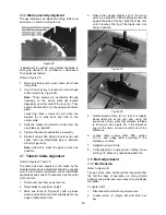
Figure 33 


Figure 34 

When ripping long boards, use a support at front of 
table (C, Figure 34), such as a roller stand, and a 
support or "tailman" at the rear (D). 

Never use the rip fence beyond the point where the 
carriage is flush with the end of the rails. 

Have the blade extend about 1/8" above the top of 
the workpiece. Exposing the blade above this point 
can be hazardous. 

10.3

  Resawing 

Resawing  is  a  ripping  operation  in  which  thick 
boards are cut into thinner ones. Note: A band saw 
is the ideal tool for resawing. 


If  the  table  saw  is  used  for 

resawing,  take  precautions  such  as  using  an 
auxiliary fence, resaw barrier or similar devices 
to stabilize the workpiece and provide operator 
safety.  

Narrow boards up to 3" can be resawn in one pass. 
Wider  boards  up  to  6"  must  be  resawn  in  two 
passes. 

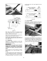
In  resawing  wider  boards,  adjust  the  blade  height 
so as to overlap the two cuts by 1/2" as shown in 
Figure 35. Too deep a first cut can result in binding 
and possible kickbacks on the second cut. Always 

use  the  same  side  of  the  board  against  the  fence 
for both cuts. 


Figure 35 

10.4

  Crosscutting 

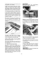
Crosscutting  is  where  the  workpiece  is  fed  cross 
grain  into  the  saw  blade  using  the  miter  gauge  to 
support and position the workpiece (Figure 36). 


Figure 36 

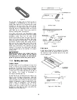
Crosscutting  should 

never 

be  done  freehand  nor 

should the fence be used as an end stop unless an 
auxiliary  block  (E,  Figure  37)  is  clamped  to  the 
front  of  the  blade  area  such  that  the  cutoff  piece 
comes free of the block before cutting begins. 


Figure 37 


Summary of Contents for 1791000K

Page 1: ...rts Manual 10 inch Cabinet Saw Model PM1000 Powermatic 427 New Sanford Road LaVergne Tennessee 37086 Part No M 1791000 Ph 800 274 6848 Revision B 01 2019 www powermatic com Copyright 2015 Powermatic This pdf document is bookmarked ...

Page 2: ... a product requires further inspection the Technical Service representative will explain and assist with any additional action needed Powermatic has Authorized Service Centers located throughout the United States For the name of an Authorized Service Center in your area call 1 800 274 6846 or use the Service Center Locator on the Powermatic website More Information Powermatic is constantly adding ...

Page 3: ...button 15 8 4 Extension cords 15 8 5 Magnetic switch and safety key 15 9 0 Adjustments 16 9 1 Tools required for adjustments 16 9 2 Fence alignment 16 9 3 Blade raising tilt mechanism 16 9 4 Miter gauge 16 9 5 Blade tilt stop adjustment 17 9 6 Riving knife alignment 18 9 7 Table to blade alignment 19 9 8 Belt adjustment 19 9 9 Arbor Arbor Bearing Removal 20 10 0 Operations 20 11 0 Safety devices 2...

Page 4: ... guard to remind the operator of the dangers of improper machine operation 15 Check damaged parts Before further use of the machine a guard or other part that is damaged should be carefully checked to determine that it will operate properly and perform its intended function Check for alignment of moving parts binding of moving parts breakage of parts mounting and any other conditions that may affe...

Page 5: ...ece which will reduce the chance of kickback Never attempt freehand cuts The workpiece must be fed parallel to the blade otherwise kickback will likely occur Always use the rip fence or miter gauge to support the workpiece Make sure that rip fence is parallel to blade If not the chances of kickback are very high Take the time to check and adjust the rip fence Feed cuts through to completion Anytim...

Page 6: ... constructed to provide consistent long term operation if used in accordance with the instructions as set forth in this document This manual is not intended to be an exhaustive guide to table saw operational methods use of jigs or after market accessories choice of stock etc Additional knowledge can be obtained from experienced users or trade articles Whatever accepted methods are used always make...

Page 7: ...sulting in a cut that does not protrude through the top of the workpiece includes Dado and rabbet cuts The blade guard and riving knife must be re installed after performing a non through cut to avoid accidental contact with the saw blade during operation Parallel Position of the rip fence equal in distance at every point to the side face of the saw blade Perpendicular 90 right angle intersection ...

Page 8: ...or lock yes Arbor wrench included combination 17 27 mm Maximum depth of cut at 90 degrees 3 1 8 79 mm Maximum depth of cut at 45 degrees 2 1 8 54 mm Maximum rip to right of blade 30 or 52 Maximum rip to left of blade 12 305 mm Dado maximum width 13 16 20 6 mm Dado maximum diameter 8 200 mm Blade height per one revolution of handwheel 19 64 7 5mm for 90 1 16 1 7 mm for 45 Blade tilt left 0 to 45 de...

Page 9: ...ed with 30 Rail Fence 330 lb 150 kg Saw assembled with 52 Rail Fence 335 lb 152 kg L length W width D depth H height The specifications in this manual were current at time of publication but because of our policy of continuous improvement Powermatic reserves the right to change specifications at any time and without prior notice without incurring obligations ...

Page 10: ...gs are shipped in separate cartons Read and understand all assembly instructions before attempting assembly The saw must be disconnected unplug from power during assembly Failure to comply may cause serious injury 7 2 Tools required for assembly Hex keys 3 and 4mm Open end wrenches 14 and 17mm Cross point screwdriver Straight edge Rubber mallet or hammer with block of wood Note A ratchet wrench so...

Page 11: ... Install handle I onto each handwheel using 14mm wrench on the flat to tighten it 3 Install storage hooks F with two button head screws and washers HP 4 5 6 The hooks are used to store the Accu Fence when it is not in use 4 Tilt arbor using right handwheel and remove Styrofoam packing from around motor Figure 3 7 5 Installing table extensions Refer to Figure 4 1 Attach an extension wing to saw tab...

Page 12: ...5Z that accompanies the fence NOTE The switch bracket must be mounted to front rail before installing guide tube Follow instructions in section 7 8 then install guide tube 7 8 Switch bracket Refer to Figure 7 After front rail has been installed mount switch bracket with three flat head screws HP 7 Mount guide tube to front rail referring to instructions in your Accu Fence manual Figure 7 7 9 Wood ...

Page 13: ...t in the arbor Simultaneously remove arbor nut A loosen with arbor wrench if necessary 6 Remove flange B 7 Install blade onto arbor making sure the teeth point downward toward front of saw 8 Install flange B and nut A 9 Engage arbor lock C and tighten nut A with provided arbor wrench Figure 10 Figure 11 blade not provided 7 13 Riving knife Refer to Figure 12 To install riving knife 1 Remove table ...

Page 14: ...ial health issues due to dust inhalation Attach dust collection hose to the 4 inch dust port at base of saw and secure with a wire hose clamp not provided 8 0 Electrical connections The PM1000 table saw is rated at 115 230V power and is pre wired for 115 volt The table saw comes with a plug designed for use on a circuit with a grounded outlet that looks like the one pictured in A Figure 13 Before ...

Page 15: ... the incoming power leads for 230 volt operation follow wiring diagram on inside cover of motor junction box A Figure 14 A similar diagram is found in section 16 0 of this manual In case of discrepancy diagram in junction box takes precedence The plug on the end of the motor cord must be replaced with a UL CSA listed plug rated for 230V 8 3 Overload reset button If saw becomes overloaded and the m...

Page 16: ...ten lock knob The blade should be adjusted about 1 8 above top surface of material being cut To tilt blade turn lock knob C counter clockwise to loosen turn handwheel D until desired angle is obtained as shown on tilt scale Retighten lock knob C Figure 16 9 4 Miter gauge Refer to Figures 17 and 18 9 4 1 Setting miter angle The precision miter gauge has a rack and pinion adjustment for setting the ...

Page 17: ...e above procedure does not satisfactorily align the miter gauge loosen two screws J Figure 18 beneath mounting block and shift block as needed Retighten screws when finished Figure 18 NOTE The bar of the miter gauge has two slots with set screws H Figure 17 Adjust these set screws 4mm hex key to eliminate any play between bar and miter slot 9 5 Blade tilt stop adjustment The stops for 90 45 blade ...

Page 18: ...awl assemblies and table insert 2 Place a straightedge A Figure 23 on the table so it rests against blade B and riving knife C Rotate blade so that top of blade tooth touches straightedge Figure 23 The saw blade and riving knife must be in line If adjustment is needed 3 Pull quick release lever A Figure 24 and remove riving knife making note as to which direction riving knife needs to be moved to ...

Page 19: ...cuts become inaccurate check table blade squareness and correct if necessary Use the miter slot to do this 1 Disconnect saw from power source 2 Raise blade to maximum height 3 Mark one tooth A Figure 27 with a grease pencil and position the tooth slightly above top edge of table at the front 4 Raise miter gauge slightly out of its slot to serve as a shoulder Using a sliding square B against the si...

Page 20: ... are conditions which can cause kickbacks Confining the cutoff piece when crosscutting or ripping Releasing workpiece before completing operation or not pushing workpiece all the way past saw blade Not using splitter riving knife when ripping or not maintaining alignment of splitter riving knife with saw blade Using dull saw blade Not maintaining alignment of rip fence so that it tends to angle to...

Page 21: ...emove the cutoff piece with the saw blade rotating Figure 31 Always use blade guard splitter riving knife and anti kickback pawls Make sure splitter riving knife is properly aligned When wood is cut along the grain the kerf tends to close and bind on the blade and kickbacks can occur Note A warning decal is affixed to the guard to remind the operator of some basic safety procedures The rip fence A...

Page 22: ...ize the workpiece and provide operator safety Narrow boards up to 3 can be resawn in one pass Wider boards up to 6 must be resawn in two passes In resawing wider boards adjust the blade height so as to overlap the two cuts by 1 2 as shown in Figure 35 Too deep a first cut can result in binding and possible kickbacks on the second cut Always use the same side of the board against the fence for both...

Page 23: ...the blade extend about 1 8 above the top of the workpiece Exposing the blade above this point can be hazardous 10 5 Bevel and miter operations Bevel cut A bevel cut is a special type of operation where the saw blade is tilted at an angle less than 90 degrees to the table top Figure 39 Operations are performed in the same manner as ripping or crosscutting except the fence or miter gauge should be u...

Page 24: ...a dado head in a tilted position Never operate the saw without the blade guard riving knife and anti kickback pawls for operations where they can be used 11 0 Safety devices Feather board Feather boards can be purchased at most tool stores or made by the operator to suit particular applications The feather board Figure 42 should be made of straight grain hardwood approximately 1 thick and 4 to 8 w...

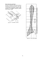
Page 25: ...dded level of safety for the operator A push stick is included with your table saw but you may wish to make others personalized for different cutting procedures The templates in Figures 44 and 45 offer construction details Figure 44 Push Block Template Figure 45 Push stick template ...

Page 26: ...nt should provide rust protection for the surface without staining workpieces Clean the motor housing with compressed air Wipe down the fence rails with a dry silicon lubricant Periodic Keep the inside of the cabinet and trunnion area clean Check for excessive play in the tilting and raising mechanism and in the saw arbor and adjust as required Check for belt tension and wear Adjust or replace bel...

Page 27: ...ur table saw Contact your dealer to order or call Powermatic at the phone number on the cover Figure 46 708097 Dado Insert Figure 47 708119 Universal Mobile Base adjustable up to 36 x 36 708158 Mobile Base Extension Kit Figure 48 708295 Tenoning Jig Figure 49 1791793 Low Profile Thin Kerf Riving Knife 0 079 ...

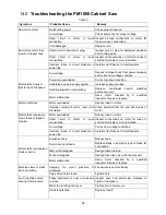
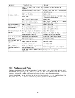
Page 28: ...d by a qualified inspector Repair or replace Motor overheats Motor overloaded Reduce load on motor Improper cooling of motor lack of air circulation Clean sawdust from fan and duct areas of motor Motor stalls resulting in blown fuses or tripped breaker Motor overloaded Reduce load on motor Short circuit in motor or loose connections Inspect connections on motor for loose or shorted terminals or wo...

Page 29: ... down the right side of pointer bracket until blade can reach 90 degrees Cuts out of square when crosscutting Miter gauge out of adjustment Re set stops and pointer on gauge Miter slot misaligned Realign table to blade Cuts not true at 90 or 45 degrees Stop screws not set properly Readjust screws Tilting or raising handwheel difficult to turn Lock knob not released Loosen lock knob Worm and trunni...

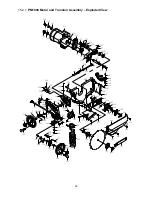
Page 30: ...31 31A optional 30 33 34 35 36 24 27 28 29 23 25 26 37 38 38 39 40 42 43 45 45 43 46 46 28 48 28 48 49 50 52 47 53 54 56 55 54 51 51 57 58 58 59 60 60 62 67 67 61 44 47 47 63 64 1 2 3 4 5 5 6 7 7 8 9 9 10 11 12 13 14 15 16 17 18 19 20 21 22 41 41 38 1 65 34 35 66 ...

Page 31: ... TS 1550041 Flat Washer M6 8 29 TS 1482011 Hex Cap Screw M6 x 10 4 30 PM1000 030 Table 1 31 PM1000 031 Table Insert 1 31A 708097 Dado Insert Optional 1 32 TS 0267021 Socket Set Screw 1 4 x 1 2 6 33 PM1000 033 Extension Wing 2 34 TS 1550071 Flat Washer M10 10 35 TS 2361101 Lock Washer M10 10 36 TS 149105 Hex Cap Screw M10 x 35 6 37 PM2000 132 Dust Chute 1 38 PM1000 038 Button Head Socket Screw M6 x...

Page 32: ...05 Powermatic Logo 1 62 LM000636 Warning Label 1 63 PM2700 441 Top Stripe 40 L 2 64 PM2700 440 Bottom wide Stripe 40 L 2 65 PM2000 121 Dust Port 1 66 TS 1482011 Hex Cap Screw M10 x 20 4 67 TS 0254011 Button Head Socket Screw 1 4 x 3 8 2 PM2000 135 Push Stick not shown 1 PM1000 HP Hardware Package see sect 7 1 2 for contents ...

Page 33: ... 132 130 130 128 130 133 134 136 135 109 137 138 139 139 140 141 140 142 143 144 145 146 147 148 148 149 150 150 151 152 154 149 146 155 156 157 158 130 109 147 159 160 160 161 163 162 164 164 165 160 166 166 167 168 169 170 171 172 173 174 175 176 177 178 180 145 145 145 145 181 182 183 145 145 184 187 140 179 153 117 119 121 118 123 127 130 129 185 186 186 122 136 190 188 191 189 ...

Page 34: ...hown 1 PM1000 115DC Dust Cover not shown 1 116 PM1000 116 Shaft 1 117 TS 2249202 Button Head Socket Screw M10 x 20 1 118 TS 2361101 Lock Washer M10 2 119 PM1000 119 Brass Flat Washer M24 1 120 PM1000 120 Nylon Nut M22 1 121 TS 1550071 Flat Washer M10 1 122 PM1000 122 Bracket 1 123 TS 1491021 Hex Cap Screw M10 x 20 1 124 PM1000 124 Center Trunnion 1 125 PM1000 125 Pin M10 x 40 2 126 PM1000 126 Rear...

Page 35: ...ndle 1 170 TS 1541021 Nylon Nut M6 1 JTAS10L 179A Arbor Lock Insert Assembly index 171 thru 175 1 171 JTAS10L 179 3 Insert Bracket 1 172 TS 1503051 Socket Head Cap Screw M6 x 20 2 173 JTAS10L 179 2 Spring 1 174 JTAS10L 179 1 Locking Pin 1 175 TS 1521031 Socket Set Screw M4 x 8 1 176 PM1000 176 Pilot Link Plate 1 177 PM1000 177 Special Screw 1 4 20UNC x 12 1 178 PM1000 178 Special Screw 3 8 24UNF x...

Page 36: ...36 15 3 1 PM1000 Blade Guard Assembly Exploded View 1 3 2 4 5 5 6 7 8 9 10 11 11 12 13 13 14 15 15 16 17 16 16 16 18 17 20 19 19 19 19 21 23 22 24 7 25 26 17 17 27 1A 1B ...

Page 37: ...9 PM2000 313 Roll Pin M5 x 25 1 10 PM2000 310 Top Shield 1 11 TS 081B012 Pan Head Screw M4 x 8 2 12 PM2000 309 Bushing 1 13 PM1000 313 Roll Pin M5 x 8 2 14 JTAS10L 304 Blade Guard Side Shield 2 15 PM1000 315 Linking Plate 4 16 TS 1514021 Flat Head Socket Screw M6 x 16 8 17 TS 1550061 Flat Washer M6 8 18 TS 1521041 Socket Set Screw M4 x 10 1 19 TS 1541021 Nylon Insert Lock Nut M6 8 20 PM1000 320 Ro...

Page 38: ...38 16 0 Electrical Connections for PM1000 ELECTRICAL SCHEMATIC 115V 70uf 250 VAC 300MFD 125 VAC ELECTRICAL SCHEMATIC 230V 70uf 250 VAC 300MFD 125 VAC ON OFF Switch ON OFF Switch ...

Page 39: ...39 This page intentionally left blank ...

Page 40: ...40 427 New Sanford Road LaVergne Tennessee 37086 Phone 800 274 6848 www powermatic com ...

Reviews: