


T
T
H
H
E
E
W
W
O
O
R
R
L
L
D
D
L
L
E
E
A
A
D
D
E
E
R
R
I
I
N
N
C
C
O
O
M
M
P
P
A
A
C
C
T
T
M
M
A
A
T
T
E
E
R
R
I
I
A
A
L
L
H
H
A
A
N
N
D
D
L
L
I
I
N
N
G
G
S
S
O
O
L
L
U
U
T
T
I
I
O
O
N
N
S
S
17 of 21
Sept/20
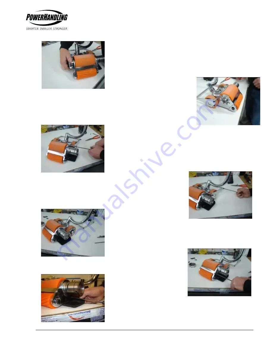
◄
Figure 7
Remove the bearing housing.
►
Figure 8
PowerHandler shown with
bearing housing removed.
◄
Figure 9
With a 4mm Allen wrench, remove
the front bolt on the motor side of
the tip preventer.
►
Figure 10
Loosen the rear bolt on the motor
side of the tip preventer.
◄
Figure 11
Rotate the tip preventer side
plate back.
►
Figure 12
Using a 5mm Allen wrench, remove
the muffler retainer bolts.
◄
Figure 13
Remove the muffler retainer.