background image

4

Maintenance (continued)

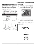
Inserting tip seals


NOTE:

 Tips seals for Fixed Scroll and Orbit Scroll have opposing 

seal cut angles (See NOTE and explanatory diagram below).

Insert tip seal so that the lip of tip seal is on the bottom of 
seal groove and inner side of involute and the direction of lip 
faces the center of involute (curving spiral). See Figure 5. This 
is to be done for both FS and OS sets. 

Use caution not to tear or distort lip.

1.  Insert new HP tip 

seal from the center 
section for OS or Orbit 
Scroll so that there 
will be no clearance at 
the tip (start) section 
(See Figure 5 and 6).

2.  Insert so that new LP 

tip seal will contact 
closely with HP tip 
seal inside Scroll 
Groove (See Figure 4 
on page 4).


Insert approximately half of the LP tip 

  seal and remove the tip seal to confi rm 

that a notch in the tip seal has been created. This will prevent 
movement during installation (See Figure 7).

 3.  Repeat the same procedure for FS or Fixed Scroll tip seal 

set, remove both the dust seal and backup tube located 
on outermost side FS set.

4.  Insert new backup tube in the FS Scroll in the 6 o’ clock 

position (See Figure 8).

5.  Insert new dust seal on the backup tube.

6.  After replacing tip seal set, reassemble Fixed Scroll set 

to the Orbit Scroll. Tighten nuts and bolts temporarily 
and confi rm if crankshaft rotates smoothly by hand and 
tighten them fi rmly. Tightening torques are: 


NOTE:

 Assemble so that dust seal and tip seal will not drop 

between Orbit Scroll set and Fixed Scroll set.

Figure 6

Figure 7

Machined 

To Avoid Movement 

During Installation

Figure 5

Enter 
side

Lip Direction

Lip Side
(Grooved bottom)

Lip Surface 
(Inside)

Bolt

Torque First 

Second

SLAE03EB 

17 in lb. 

265 in lb.

SLAE05E / SLAE05EHP  

17 in lb. 

265 in lb.

Figure 8

Back-up Tube

Dust Seal

Scroll Air Compressor Service and Maintenance

Summary of Contents for SLAE03EB

Page 1: ...ng during this process so the 180 phase relationship of the scrolls is maintained The compressor s inlet is at the outer boundary of the scrolls The compressed gas is discharged through the outlet at the center of the fixed scroll so no valves are needed Safety Guidelines This manual contains information that is very important to know and understand This information is provided for SAFETY and to P...

Page 2: ...volume of grease as indicated on the grease delivery chart See Grease Delivery chart on Page 2 and on Figure 1 Use only Powerex genuine grease Pump grease gun before feeding This eliminates air from the grease passage of the extension adapter 4 Replace plastic dust cap Greasing Pin Crank Bearings The bearings on the scroll compressor are regreaseable to allow extended compressor life Service shoul...

Page 3: ...firmation of the Parts 1 Confirm if the tip seal set you purchased is correct for the air end you are repairing See part number 12 on Page 7 for tip seal set and corresponding pump model number One tip seal set contains all of the items in Figure 3 below 2 Confirm if the following parts are included See Figure 3 1 2 5 6 4 3 Figure 3 Tip Seal Removal Figure 4 Item No Description Qty 1 HP tip seal f...

Page 4: ...otch in the tip seal has been created This will prevent movement during installation See Figure 7 3 Repeat the same procedure for FS or Fixed Scroll tip seal set remove both the dust seal and backup tube located on outermost side FS set 4 Insert new backup tube in the FS Scroll in the 6 o clock position See Figure 8 5 Insert new dust seal on the backup tube 6 After replacing tip seal set reassembl...

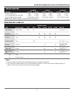
Page 5: ...according to maintenance schedule 2 The maintenance schedule relates to the normal operating conditions If the circumstances and load condition are adverse shorten the cycle time and do maintenance accordingly MAINTENANCE SCHEDULE GREASE DELIVERY SLAE03EB SLAE05E SLAE05EHP Bearing 1st Time 2nd Time 1st Time 2nd Time 1st Time 2nd Time Orbit Scroll Bearing 5 Times 4 Times 7 Times 6 Times 7 Times 6 T...

Page 6: ...6 Scroll Air Compressor Service and Maintenance Maintenance Log Date Maintenance Required Maintenance Performed ...
Page 7: ...7 Scroll Air Compressor Service and Maintenance Maintenance Log Date Maintenance Required Maintenance Performed ...

Page 8: ...8 Scroll Air Compressor Service and Maintenance Figure 9 Compressor Parts 6 1 3 4 2 12 5 7 11 8 10 FS cover 14 15 13 13a 9 ...
Page 9: ...AV IP602000AV 1 9 Fan Duct Gasket 2 IP602400AV IP602400AV IP602400AV 1 10 Long Nipple 96647011 96647011 96647011 1 11 Dust Cap IP603500AV IP603500AV IP603500AV 1 12 Tip Seal Set 92834090 92832070 92832080 1 13 Filter Assembly ST073925AV ST073925AV ST073925AV 1 13a Filter Element ST073921AV ST073921AV ST073921AV 1 14 Adaptor Plate IP088400AV IP088400AV IP088400AV 1 15 Intake Gasket IP088200AV IP088...

Page 10: ...10 Scroll Air Compressor Service and Maintenance Notes ...

Page 11: ...hs from the date of shipment by Powerex or thirty six 36 months from the documented date of startup or ten thousand 10 000 hours of use whichever occurs first Supplier s repair or replacement of any Product shall not extend the period of any warranty of any Product This warranty applies to the exchange of part s found to be defective by an Authorized Powerex Service Representative only d Replaceme...

Page 12: ...stallation and or use of Products for certain purposes which may vary from those in neighboring areas While Powerex attempts to assure that its Products comply with such codes it cannot guarantee compliance and cannot be responsible for how the product is installed or used Before purchase and use of a Product please review the Product applications and national and local codes and regulations and b...

Reviews: