D:\manual\UM_PCM-WOW\UM_WOW-300(S)\661-WOW3-000-31.doc
- 7 -
3.4 Checking table for Buzzer, LED and Status.
4.
S
OFTWARE AND
C
OMPUTER
I
NTERFACE
(O
PTION
)
4.1 Power Monitoring Software
The UPSMON series software (or other power monitoring software) is applied
standard RS-232 interface to perform monitoring functions, and then provides an
orderly shutdown of a computer in the event of power failure. Moreover, UPSMON
displays all the diagnostic symptoms on monitor, such as Voltage, Frequency,
Battery level and so on. The software is available for DOS, Windows 3.1x, Windows
95/98/2000/me, Windows NT V3.5 or later, Novell Netware and others. Call your
dealer for more information on computer OS compatible solutions.
4.2 Interface Kits
A series of interface kits is available for operation systems that provide UPS
monitoring. Each interface kit includes the special interface cable required to convert
status signals from the UPS into signals which individual operating system
recognize. The interface cable at UPS side must be connected to REMOTE PORT,
at computer side can be either COM 1 or COM 2. The other installation instructions
and powerful features please refer to READ.ME file.
CAUTION:
Use only factory supplied or authorized UPS monitoring cable!
4.3 The characteristics of computer interface port
The computer interface port has the following characteristics:
The communication port on the back of the UPS may be connected to host
computer. This port allows the computer to monitor the status of the UPS and
control the operation of the UPS in some cases. Its major functions normally include
some or all of the following:
To broadcast a warning when power fails.
Buzzer
Power-on LED (GREEN)
Status
OFF ON AC
MODE
OFF
ON
:
0.5’S
OFF
:
0.5’S
BATTERY FAULT
ON
AC MODE ON
BACKUP MODE
ON
:
1’S
OFF
:
4’S
OVER LOAD
ON
:
1’S
OFF
:
4’S
ON
:
1’S
OFF
:
4’S
BACKUP
MODE
ON
:
1’S
OFF
:
1’S
ON
:
1’S
OFF
:
1’S
BATTERY
LOW
ON
:
0.5’S
OFF
:
0.5’S
ON CHARGER
ABNORMAL
D:\manual\UM_PCM-WOW\UM_WOW-300(S)\661-WOW3-000-31.doc
- 8 -
To close any open file before the battery is exhausted.
To turn-off the UPS.
Some computers are equipped with a special connector to link with the
communication port. In addition, special plug-in cord may be needed. Some
computers may need special UPS monitoring software. Contact your dealer for the
details on the various interface Kits.
Attention:
The software and Interface port function for the model name with “S”
suffix only.
5. B
ATTERY
M
AINTENANCE AND
R
EPLACEMENT
5.1 Battery maintenance
For the preventive maintenance, keep the area around the UPS clean and duty-free.
Please also keep the UPS at ambient temperature of 25
℃
(77
℉
). It is recommend
that the batteries charge for 24 hours after long storage.
5.2 Battery replacement
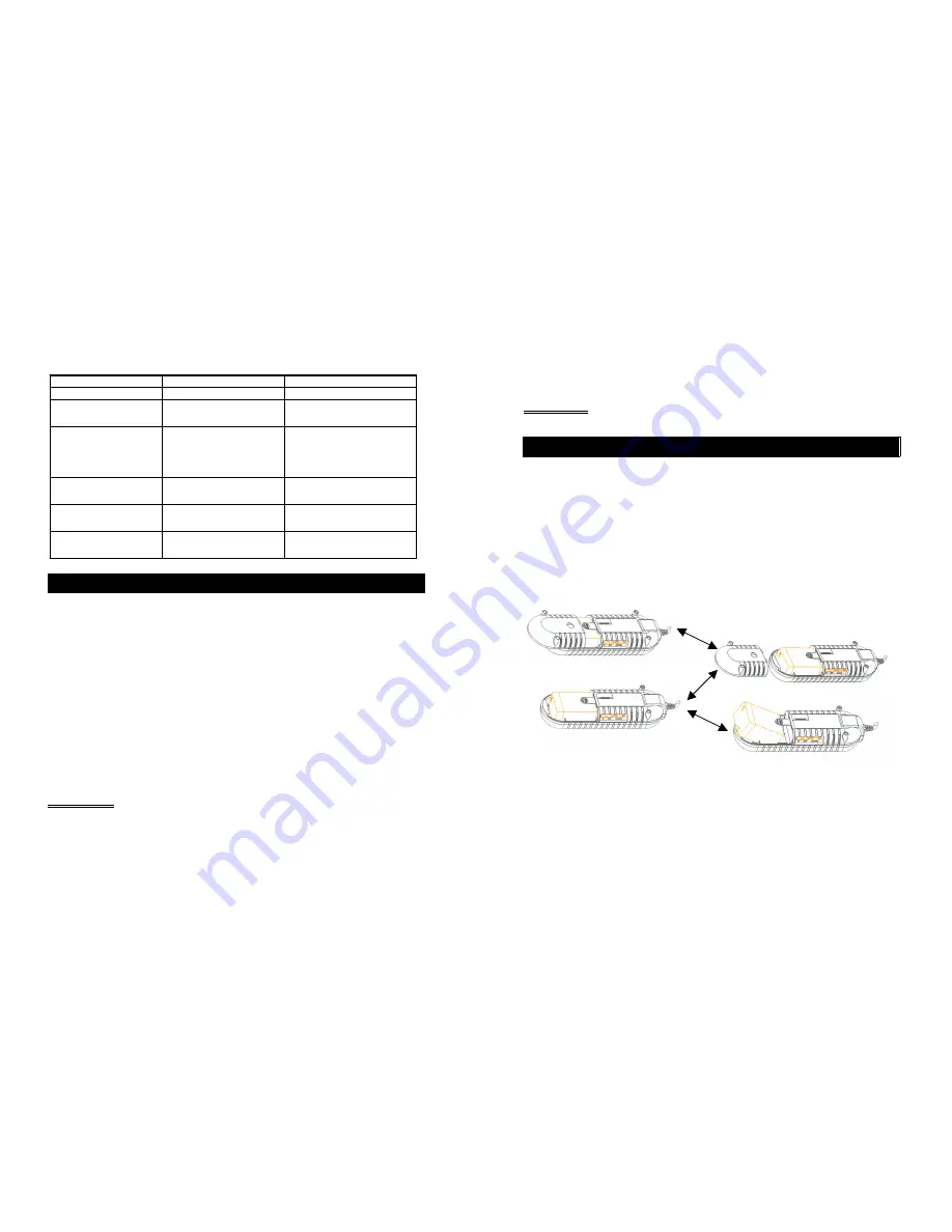
The battery should be replaced within 30 to 90 days if the Power-on indicator
flashes. To verify that the batteries need to be replaced, conduct a self-test by
pressing Power button. If the Power-on indicator continues to flash, please replace
the inner battery according to the follow procedure.
Battery Replacement Procedure
5.3 Storage
To store UPS, cover it and store it with the battery fully charged. During extended
storage, just connect the utility power to recharge the battery every three months to
ensure battery life.


