background image

Operating Instructions and Parts List,

Form No. 1000023A

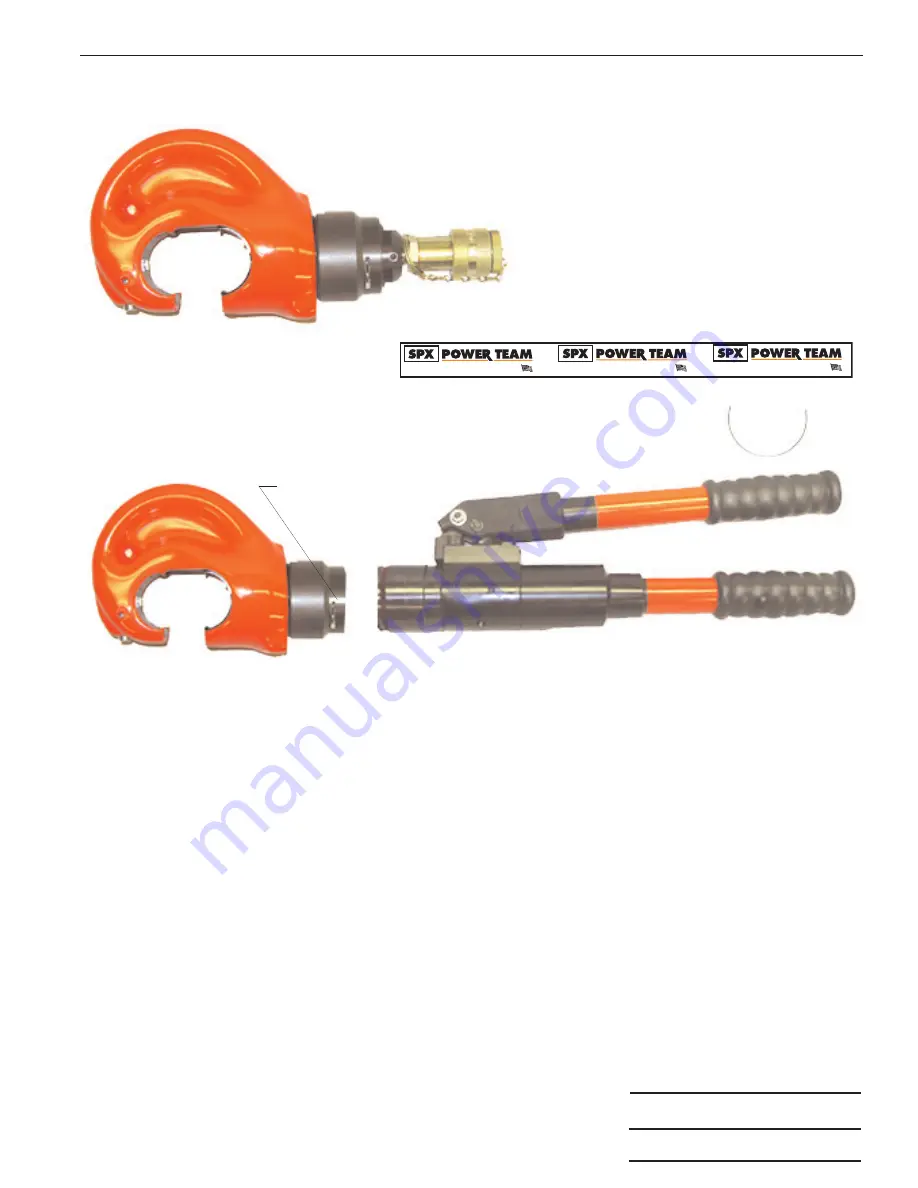
INSTRUCTIONS FOR CONVERSION TO C12-HHT

1.

Fully retract tool ram and make sure all pressure has dissipated.Disconnect tool from hose to pump.

2.

Place tool in a vise with handles pointing upward. Remove adhesive label covering slot in cylinder.

3.

Pry hooked end of retaining wire out of slot in cylinder.

4.

Holding hooked end of wire with pliers, rotate cylinder to force retaining wire out of groove and through slot.
Discard wire.

5.

Carefully separate end cap assembly from cylinder assembly, holding discharge spring in place.

6.

Apply lubricant to groove in pump block and to retaining wire.

7.

Insert pump block assembly into back end of cylinder assembly.  Rotate cylinder assembly until hole in pump
block appears in slot in cylinder.

8.

Place hooked end of new wire from conversion kit into hole in pump block.  Align free length of wire along slot
in cylinder.  Rotate cylinder assembly in opposite direction to feed wire through slot and into groove.

9.

When wire is fully engaged, hooked end will snap out of hole in pump block to permit full head rotation.
Seal slot with new adhesive label.

10.

Purge air from tool using normal fill and bleed procedures.

Sheet No.

3 of 5

Rev 1

Date: 13 June 2005

®

SPX Corporation, Rockford, IL 61109 USA
http://www.powerteam.com

Made in USA

®

SPX Corporation, Rockford, IL 61109 USA
http://www.powerteam.com

Made in USA

®

SPX Corporation, Rockford, IL 61109 USA
http://www.powerteam.com

Made in USA

WIRE SLOT IN CYLINDER

12-HTR TOOL

C HEAD SUB-ASSEMBLY

(PART NUMBER 3000084 coated

or 4-0644 uncoated)

PUMP MECHANISM SUB ASSEMBLY

(PART NUMBER 3000089)

CONVERSION ASSEMBLY

(PART NUMBER 4-0766)

1-RETAINING WIRE
1-WRAP AROUND DECAL

Summary of Contents for 12-HTR series

Page 1: ...12 HTR AND C12 HTR TOOL IS NOT TO BE USED FOR HOT LINE WORK SPECIFICATIONS TOOL SECTION 1 81 4 60 CM DIA RAM 96 2 44 CM STROKE WITH DIES CRIMPING FORCE 13 1 U S TONS AT10 000 PSI 11 9 METRIC TONS AT...

Page 2: ...ever operating hydraulic equipment Always wear hearing protection as required Operation repair or maintenance of hydraulic equipment should be performed by a qualified person who understands the prope...

Page 3: ...with the same care and attention as any other fine piece of equipment REPLACING HYDRAULIC SEALS Maintenance and repair of this tool should be provided with the same reasonable care given other fine e...

Page 4: ...several times DO NOT USE BRAKE FLUID OF ANY KIND PREVENTIVE MAINTENANCE The majority of service troubles are caused by dirt collecting about the tool or in the oil system Keep the tool clean and prev...

Page 5: ...in pump block appears in slot in cylinder 8 Place hooked end of new wire from conversion kit into hole in pump block Align free length of wire along slot in cylinder Rotate cylinder assembly in opposi...

Page 6: ...eld by a deformed washer A small amount of leakage is desirable around the ram to lubricate this parts If enough leakage occurs to cause the oil to run the packing should be replaced If the dies do no...

Page 7: ...1 Plug Dust 6 9796 1 Coupler Female 3 8 NPTF 7 3 9990 1 Cap End 8 3000084 1 C Head Ram Cylinder Assembly PVC coated 8 4 0644 1 C Head Ram Cylinder Assembly Non PVC coated ITEMS NOT SHOWN 3 1294 OR9 1...

Page 8: ...e Transfer 2 5 3245 1 Ring Back Up 3 10266 1 O Ring 4 3 9683 1 Retaining Swivel 5 11032 1 Ring Retaining 6 3 9681 1 Spring Tension 7 3 9682 1 Retainer Threaded Item Part No Item Part No No No Req d De...

Page 9: ...4 5 7 8 9 6 1 5 0007 1 Screw 2 3 4145 1 Washer Seal 3 5 1996 1 Pin Locater 4 3 1205 1 Washer 5 3 1211 1 Wiper 6 4 0649 1 Body Ram 7 3 1214 1 Ring Backup 8 5 1263 1 O Ring 9 4 1324 1 Spring Assembly 1...

Page 10: ...ng 10 11032 1 Ring Retaining Item Part No Item Part No No No Req d Description No No Req d Description 1 4 0646 1 C Head Assembly 2 3 1203 1 Screw 3 4 0645 1 Cylinder 4 3 1204 1 Key 5 5 1258 1 Lock Wa...

Reviews: