5
Power-Flo Pumps & Systems • 877-24PUMPS • www.powerflopumps.com
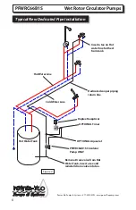
Installation
Pump Mounting
Arrows on the pump chamber indicate
direction of flow through the pump.
The pump can be mounted vertically free of
stresses from piping system with the pump
shaft in the horizontal position.
NEVER install the pump with the shaft
vertical or where the shaft falls below the
horizontal plane.
Provide support to the pump or adjacent
plumbing to reduce thermal and mechanical
stress on the pump.
Installation Requirements
1. Thoroughly clean and flush the system prior
to pump installation.
2. Do not install the pump at the lowest point
of the system where dirt and sediment collect.
3. Ensure that water does not enter the
terminal box during the installation.
4. (Open System) Install the pump in the
supply line; the suction side of the pump
should be flooded with water. Ensure that the
static head requirement from chart is achieved.
5. If there are execessive suspended particles
in the water, it is recommended that a strainer
and/or filter be installed and cleaned regularly.
6.
DO NOT START THE PUMP UNTIL THE
SYSTEM HAS BEEN FILLED.
Start-Up
Do not use the pump to vent the system. Do
not start the pump before filling the system.
NEVER OPERATE THE PUMP DRY
.
Electrical:
This pump will come equipped with a 6 Ft.
long soft jacketed 3 prong electric cord and
strain relief connection for “outlet plug in”
installations. The pump must be within 6 foot
of a 115 volt receptacle.
Operating voltage and other electrical
data can be found on the nameplate. All
models have thermal protection and require
no additional external protection. The
temperature of the winding will never exceed
allowable limits, even in locked rotor.
Operation
These circulating pumps will operate quietly
and efficiently and provide years of service if
sized for correct performance and installed
properly. Under
NO
circumstances should the
pump be operated without water circulation
or without the minimum required inlet
pressure for prolonged periods of time. This
could result in motor and pump damage.
Failure To Operate
When the pump is first started, the shaft may
rotate slowly until water has fully penetrated
the bearings. If the pump does not run, the
shaft can be rotated manually. To accomplish
this, switch off the electrical supply and close
the isolation valves on each side of the pump.
Remove the indicator plug in the middle of the
nameplate. Insert a small flat blade screwdriver
into the end of the shaft and gently turn until
the shaft moves freely. Replace and tighten the
plug. Open the isolation valves and wait 2 to
3 minutes for the system pressure to equalize
before starting the pump.
Wet Rotor Circulator Pumps
PFWRC66B1S


