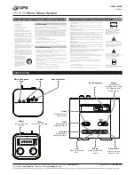
13. Mix out: Output jack for both channels
14. Output jack channel B
15. Output jack channel A
16. Power inlet, 12-15Vdc
17. AC power input
18. Balance outputs
Receiver LCD display panel:
19. RF signal receipt display
20. AF signal volume display
21. Display the current frequency channel
22. RF antenna signal status
23. Frequency display
24. LOCK: Pressing keys will not change the current feature setting of the system
HANDHELD TRANSMITTER
25. Tube body: the top contains the element, the tube the transmitting pcb, battery and
antenna.
26. Power LED: Lights when the transmitter is activated.
27. Power switch
28. Battery compartment, remove batteries in case of long time no use (prevent leakage).
29. IR signal emission LED. To learn the IR system the ideal distance is 10 cm.


