background image

CONFIDENTIAL

17

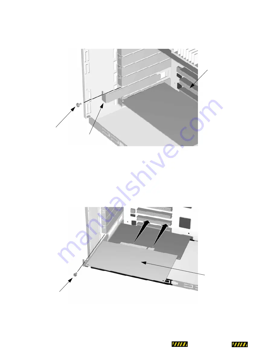
4. Hold the PCI card (contacts facing down) with one hand at each end. Notice that there is a notch 

in the contact edge of the PCI card. 

5. Lower the PCI card squarely into the PCI riser card so that the notch in the PCI card lines up with 

the notch in the PCI riser card. Slide the contacts straight into the PCI riser card and make sure 
the contacts are firmly seated. (

see 

Figure 11: PCI card installation 

on page 17).

 When properly 

seated, the contacts on the bottom should not be visible. Secure the PCI card to the chassis with 
the retaining screw.

N

N

N

Nooo

otttteee

e::::

 DonÕt force the PCI card into the slot; if the PCI riser card starts bending significantly, pull the

PCI card out, reposition it, and try again.

Slot cover screw

PCI slot cover

PCI slot

Figure 10: Removing PCI 
slot cover

Figure 11: PCI card 
installation

PCI card

Slot cover screw

Summary of Contents for Minitower 132

Page 1: ...oving and installing RAM Page 9 Removing and installing VRAM Page 11 Removing and installing CPU card Page 13 Removing and installing L2 cache Page 15 Removing and installing PCI expansion cards Page 16 Removing and installing PCI Riser card Page 19 Drive Removal Installation Procedures Removing and installing drives in the 3 5 inch drive bay Page 21 Removing and installing drives in the 5 25 inch...

Page 2: ...pansion slots Floppy Drive One 3 5 inch 1 4MB floppy disk drive Supports MacOS Windows DOS OS 2 and ProDOS disk formats Video Internal video with both Mac and SVGA connections 1MB VRAM built in and upgradeable to 4MB max Optional high quality accelerated video cards Audio 16 bit 44 1 KHz Stereo in out connections microphone port requires line level input such as AppleÕs Plaintalk Microphone Built ...

Page 3: ...ing ESD Electrostatic Discharge There are two means by which a technician can maintain a ground and eliminate ESD wear an ESD wrist strap that is grounded to the computer power down the computer but leave the CPU power cord plugged into the wall socket touch the metal case of the power supply to ensure complete static discharge before service Do not wear loose clothing or jewelry that may become c...

Page 4: ...p in the memory control panel etc Machine will not power up Machine powers up but does not chime or boot A serial port remains inaccessible even after booting without extensions resetting parameter RAM etc Machine will power down for no apparent reason After adding any hardware to the inside of the machine Resetting CUDA 1 Shut down the computer and disconnect all external devices but leave the po...

Page 5: ...CONFIDENTIAL 5 MLB DIAGRAM MLB DIAGRAM MLB Diagram ...

Page 6: ...e computer 3 Push the cover back and away from the machine chassis Lift the cover up and remove from the chassis Installing the Chassis Cover 1 With the computer upright place the cover over the chassis Push the cover towards the front of the chassis The front lip of the cover will engage the chassis frame 2 Replace the four thumb screws from the rear of the computer 3 Reconnect the cables to the ...

Page 7: ...fore the front bezel can be removed The screws are located on the inside of the chassis frame one is on the top left end of the chassis one is in the left middle of the chassis one is on the bottom left end of the chassis one is on the top right end of the chassis one is in the right middle of the chassis one is on the bottom right end of the chassis Gentlypullthebezeldirectlyforwardtodisengage La...

Page 8: ... ports on the main logic board 2 Screw the bezel to the chassis front with the six retaining screws 3 Replace the MLB protection plate on the closed side of the chassis 4 Replace the chassis cover refer to Chassis Cover Removal Installation on page 6 Figure 3 Removing retaining screws retaiing screws ...

Page 9: ...3 on page 9 Loosen the desired DIMM module by reaching in and pushing down on the small lever at the end of the DIMM slot see Figure 4 Removing RAM on page 9 The DIMM should pop loose from the slot at the lever end 4 Grasp the DIMM module on each end and evenly pull the module up and out of the slot Installing RAM 1 Hold the module with the contacts down with one hand at each end Notice that there...

Page 10: ...ble N N N No o o ot t t te e e e DonÕt force the DIMM module into the slot if the MLB starts bending significantly pull the DIMM out reposition it and try again If the DIMM module is seated correctly the lever at the end of the DIMM slot should be completely raised 3 Reset the CUDA refer to CUDA Reset on page 4 4 Replace the chassis cover refer to Chassis Cover Removal Installation on page 6 Figur...

Page 11: ...assis cover refer to Chassis Cover Removal Installation on page 6 2 Place the unit on its side with the MLB on the bottom and the open side facing up 3 Locate the VRAM DIMM s you would like to remove refer to MLB Diagram on page 5 Loosen the desired DIMM module by reaching in and pushing down on the small lever at the end of the DIMM slot see Figure 6 on page 11 The DIMM should pop loose from the ...

Page 12: ...ated the contacts on the bottom should not be visible N N N No o o ot t t te e e e DonÕt force the DIMM module into the slot if the MLB starts bending significantly pull the DIMM out reposition it and try again If the DIMM module is seated correctly the lever at the end of the DIMM slot should be completely raised 3 Reset the CUDA refer to CUDA Reset on page 4 4 Replace the chassis cover refer to ...

Page 13: ...support beam Lift the assembly out of the machine and set it aside N N N No o o ot t t te e e e The riser arm may be removed if necessary 5 Place both hands on either side of the CPU card and lift up Sometimes a gentle rocking motion from end to end not side to side will make it easier to remove the CPU card Installing the CPU 1 Hold the CPU card contacts facing down with one hand at each end Noti...

Page 14: ...N N N No o o ot t t te e e e DonÕt force the CPU card into the slot if the MLB starts bending significantly pull the CPU card out reposition it and try again 3 Replace the CPU fan assembly by lining up the tab and sliding the entire assembly toward the rear of the chassis 4 Reconnect the CPU fan to the main logic board Route the cable so it does not contact the chips on the RAM DIMMs 5 Reset the C...

Page 15: ...king motion from end to end not side to side will make it easier to remove the cache card Installing the Cache 1 Hold the L2 cache card contacts facing down with one hand at each end Notice that there are notches in the contact edge of the L2 cache card 2 Lower the L2 cache card squarely into the slot so that the notches in the L2 cache card line up with the notches in the slot Slide the contacts ...

Page 16: ...ay be attached to the PCI card 4 Remove the screw attaching the PCI card to the inside of the chassis 5 Firmly grasp the PCI card and pull it straight out of the computer laterally Be careful not to damage any components that may be protruding through the I O slot Sometimes a gentle rocking motion from end to end not side to side will make it easier to remove the PCI card Installing PCI Cards 1 Re...

Page 17: ... card and make sure the contacts are firmly seated see Figure 11 PCI card installation on page 17 When properly seated the contacts on the bottom should not be visible Secure the PCI card to the chassis with the retaining screw N N N No o o ot t t te e e e DonÕt force the PCI card into the slot if the PCI riser card starts bending significantly pull the PCI card out reposition it and try again Slo...

Page 18: ... 18 6 Connect any wires or cables to the PCI card necessary for its proper operation 7 Reset the CUDA refer to CUDA Reset on page 4 8 Replace the chassis cover refer to Chassis Cover Removal Installation on page 6 ...

Page 19: ...sconnect the power cable to the CPU cooling fan 6 Remove the hex head screw that secures the support beam to the rear of the chassis Swing the rear end of the crossbar up then unhook it from the front of the chassis and remove it from the computer 7 Firmly grasp the PCI riser card and pull it straight out of the computer Sometimes a gentle rocking motion from end to end not side to side will make ...

Page 20: ...ed When properly seated the contacts on the bottom should not be visible 2 Replace the support cross beam and its retaining screws 3 Reconnect the power cable of the CPU cooling fan Route the cable so it does not contact the chips on the RAM DIMMs 4 Replace the screws that attach the PCI riser card to the support beam 5 Reset the CUDA refer to CUDA Reset on page 4 6 Install the chassis cover refer...

Page 21: ...Installing the 3 5 inch Drive 1 Place the drive in the mounting bracket 2 Secure the drive to the bracket with four retaining screws 3 Attach all necessary cables tothe drive 4 Remove the chassis cover refer to Chassis Cover Removal Installation on page 6 5 Reset the CUDA refer to CUDA Reset on page 4 6 Install the chassis cover refer to Chassis Cover Removal Installation on page 6 3 5 inch Drive ...

Page 22: ...5 inch Drives 1 Slide the drive half way into the front bay location making sure the cable connections are facing the rear of the computer Pushing the drive in only halfway makes cable connection easier by giving more maneauvering room behind the drive 2 Connect the cables to the drive Slide the drive in the rest of the way making sure that the drive is flush with the front of the computer 5 25 in...

Page 23: ...crews that secure the drive 4 Reset the CUDA refer to CUDA Reset on page 4 5 Install the chassis cover refer to Chassis Cover Removal Installation on page 6 Figure 13 Faceplate removal Faceplate Figure 13 Faceplate removal Faceplate ...

Page 24: ...age straight out the side of the computer 5 Remove the four screws that secure the floppy disk device to the mounting cage 6 Slide the drive out of the mounting cage Installing the Floppy Disk Drive 1 Slide the drive into the drive cage and line up the drive with the holes on the drive cage 2 Replace the four screws that secure the drive to the drive cage 3 Align the tabs on the drive cage with th...

Page 25: ...floppy disk drive cage to the5 25 inch drive cage and the front of the chassis 5 Reconnect the cable to the floppy disk drive 6 Reset the CUDA refer to CUDA Reset on page 4 7 Install the chassis cover refer to Chassis Cover Removal Installation on page 6 ...

Page 26: ...nnect the fan wire from the main logic board before removing the fan and crossbar 7 Remove the CPU card refer to Removing the CPU on page 13 8 Remove the cache card refer to Removing the Cache on page 15 9 Remove the VRAM refer to VRAM Removal Installation on page 11 10 Remove the RAM refer to RAM Removal Installation on page 9 11 Disconnect the cables attached to the MLB Disconnect the power cabl...

Page 27: ... the cable connector facing the rear of the computer 4 Install the RAM refer to RAM Removal Installation on page 9 5 Install the VRAM refer to VRAM Removal Installation on page 11 6 Install the Cache card refer to Installing the Cache on page 15 7 Install the CPU refer to Installing the CPU on page 13 8 Install the PCI Riser card and assembly refer to PCI Riser Card Removal Installation on page 19...

Page 28: ...CONFIDENTIAL 28 computer to move into place 11 Reset the CUDA refer to CUDA Reset on page 4 12 Install the chassis cover refer to Chassis Cover Removal Installation on page 6 ...

Page 29: ...ur chassis retaining screws that hold the power supply in place These screws are located on the outside rear of the computer surrounding the power supply cooling fan the first screw is located above and to the left on the chassis the second screw is located below and to the left on the chassis the third screw is located above and to the right on the chassis the fourth screwis located below and rig...

Page 30: ...t on the chassis the second screw is located below and to the left on the chassis the third screw is located above and to the right on the chassis the fourth screw is located below and right on the chassis 3 Connect the power connectors to all internal SCSI devices 4 Connect the logic board power connector to the MLB 5 Reset the CUDA refer to CUDA Reset on page 4 6 Install the chassis cover refer ...

Page 31: ... use the Mac OS Every effort has been made to ensure that the informationin the module is accurate Power Computing is not responsible for printing or clerical errors Mention of third party products is for informational purposes only and constitutesneitheranendorsementnorarecommendation PowerComputing no responsibility with regard to the performance or use of these products 1997 Power Computing Cor...

Reviews: