Powered by Safety
®
36
Maintenance
01.4IB.50023A
PowlVac® Electrically Operated 15kV Ground and Test
per Long Island Railroad Specifications
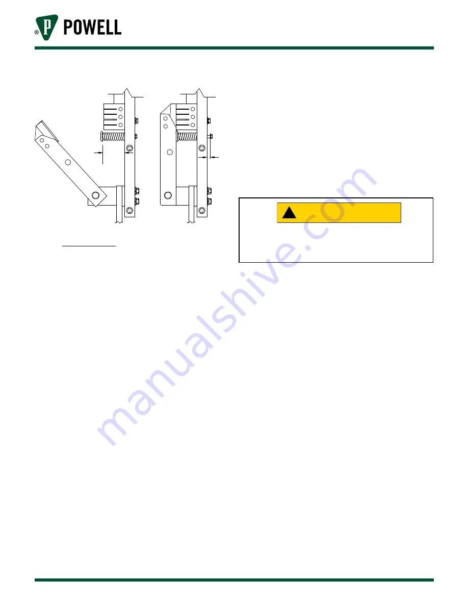
Figure 24 Ground Switch Contacts
2-1/8
1/4
to
5/16
c. Hinge Bolt
Disconnect the operating rod at the
movable contact by removing the pin.
With the movable contact not touching
the stationary contacts, apply a force
gauge to the outer end of the contacts.
should be
tightened so that the force necessary to
start the blades in motion is 9-12 lbs.
d. h
IGh
p
otentIAl
t
eStS
These tests are not ordinarily required for
routine maintenance, but should be performed
if the ground and test device has been in
storage for an extended period of time,
especially in a damp location or other adverse
environment, or if the insulation of the device
shows any signs of damage or deterioration.
1) High Voltage Insulation Integrity
With the grounding switch “
OPEN
” wire the
three upper primary stabs of the device to
a high potential test set and ground the
three lower primary stabs and the frame of
the ground and test device. Perform the
one minute high voltage test prescribed
in ANSI Standard C37.20.2, 5.5 and 4.2.3,
at the voltage level appropriate for the
equipment.
Remove all grounding conductors applied for
this test before placing the ground and test
device into service.
!
CAUTION
2) Control Voltage Insulation Integrity
If the user wishes to check the insulation
integrity of the control circuit, it may be
done with a 500V or 1000V insulation
tester or with and AC high potential tester.
The AC high potential test should be
made at 1125V, 60Hz, for one minute. The
charging motor must be disconnected at its
connection plug prior to testing the control
circuit. The motor itself may be similarly
tested at a voltage not to exceed 675V,
60Hz. Be sure to remove any test jumpers
and reconnect the charging motor when
the tests are complete.


