background image

Powered by Safety

®

3

Safety

01.4IB.51809

Ch 2  Safety

A.  S

Afe

 W

ork

 c

ondItIon

The information in Section A is quoted from  

NFPA 70E 2004 - Article 120, 120.1 Establishing an 

Electrically Safe Work Condition.

120.1 Process of Achieving an Electrically Safe 

Work Condition

1.  Determine all possible sources of electrical 

supply to the specific equipment.  Check 

applicable up-to-date drawings, diagrams, 

and identification tags.

2.  After properly interrupting the load current, 

OPEN the disconnecting device(s) for each 

source.

3.  Wherever possible, visually verify that all 

blades of the disconnecting devices are 

fully OPEN or that drawout type circuit 

breakers are withdrawn to the fully 

disconnected position.

4.  Apply lockout/tagout devices in accordance 

with a documented and established policy.

5.  Use an adequately rated voltage detector 

to test each phase conductor or circuit part 

to verify they are deenergized.  Test each 

phase conductor or circuit part both  

phase-to-phase, and phase-to-ground.  

Before and after each test, determine 

that the voltage detector is operating 

satisfactorily.

6.  Where the possibility of induced voltages 

or stored electrical energy exists, ground 

the phase conductors or circuit parts 

before touching them.  Where it could be 

reasonably anticipated that the conductors 

or circuit parts being deenergized 

could contact other exposed energized 

conductors or circuit parts, apply ground 

connecting devices rated for the available 

fault duty.

B.  S

Afety

 G

uIdelIneS

Each user has the responsibility to instruct 

and supervise all personnel associated with 

usage, installation, operation, and maintenance 

of this equipment on all safety procedures.  

Furthermore, each user has the responsibility of 

establishing a safety program for each type of 

equipment encountered.

The safety rules in this instruction bulletin are 

not intended to be a complete safety program.  

The rules are intended to cover only some of the 

important aspects of personnel safety related to  

Powell version Siemens LVAR Racking Device.

c.  G

enerAl

1.  Only supervised and qualified personnel 

trained in the usage, installation, operation, 

and maintenance of the metal-clad 

switchgear shall be allowed to work on 

this equipment.  It is mandatory that this 

instruction bulletin, any supplements, and 

service advisories be studied, understood, 

and followed.

2.  Maintenance programs must be consistent 

with both customer experience and 

manufacturer’s recommendations, 

including service advisories and instruction 

bulletin(s).  A well planned and executed 

routine maintenance program is essential 

for reliability and safety.

3.  Service conditions and applications shall 

also be considered in the development 

of safety programs.  Variables include 

ambient temperature; humidity; actual 

continuous current; thermal cycling; 

number of operations; and any adverse 

local conditions including excessive dust, 

ash, corrosive atmosphere, vermin and 

insect infestations.

Summary of Contents for 51897G31-1600

Page 1: ...01 4IB 51809 Electric Remote Racking Device 51897G31 for use with Powell Low Voltage Switchgear Equipped with Siemens Circuit Breakers Powered by Safety ...

Page 2: ...te Racking Device for Powell LV Switchgear w Siemens Circuit Breakers Contact Information Powell Electrical Systems Inc www powellind com info powellind com Service Division PO Box 12818 Houston Texas 77217 2818 Tel 713 944 6900 Fax 713 948 4569 ...

Page 3: ...he safety alert symbol is used to address practices not related to personal injury CAUTION NOTICE NOTICE is used to address practices not related to personal injury Qualified Person For the purposes of this manual a qualified person as stated in NFPA 70E is one who has skills and knowledge related to the construction and operation of the electrical equipment and installations and has received safe...

Page 4: ...Powered by Safety 01 4IB 51809 Electric Remote Racking Device for Powell LV Switchgear w Siemens Circuit Breakers This page is intentionally left blank ...

Page 5: ...tallation Operation 8 A Receiving 8 B Handling 8 C Storage 8 D Operation 9 E Inserting the Circuit Breaker into Switchgear Compartment 11 1 Racking Mechanism 11 2 Inserting the Circuit Breaker Into the Compartment 12 3 Racking the Circuit Breaker Into the Compartment 12 F Removing the Circuit Breaker from the Switchgear Compartment 13 1 Racking the Circuit Breaker out of the Compartment 13 Ch 5 Ma...

Page 6: ...V Switchgear Equipped with Siemens Circuit Breakers 6 Figure 2 Close up of Control Box 7 Figure 3 Inserting Locking Pins into Hanger Bracket 10 Figure 4 Connecting the Motor to the Control Box 10 Figure 5 Sliding the Racking Handle Assembly into Place 10 Figure 6 Activate Remote Racking Device 10 Figure 7 Racking Device Installed with Racking Handle Engaged 11 Figures ...

Page 7: ...ical working components or wiring of this equipment the power supply must be disconnected Failure to follow this warning may result in injury or death NOTICE The information in this instruction bulletin is not intended to explain all details or variations of the Powell equipment nor to provide for every possible contingency or hazard to be met in connection with installation testing operation and ...

Page 8: ...llustrations in this document are provided as general information to aid in showing component locations only All photos and illustrations are shown using deenergized equipment Be sure to follow the appropriate safety precaution while handling any of the equipment Failure to do so may result in serious injury or death WARNING To the extent required the products described herein meet the applicable ...

Page 9: ...ergized conductors or circuit parts apply ground connecting devices rated for the available fault duty B Safety Guidelines Each user has the responsibility to instruct and supervise all personnel associated with usage installation operation and maintenance of this equipment on all safety procedures Furthermore each user has the responsibility of establishing a safety program for each type of equip...

Page 10: ... LV Switchgear w Siemens Circuit Breakers D Safety Labels Warning and Caution labels are located in various places in and on the switchgear and on the circuit breaker Always observe these warnings and caution labels Do NOT remove or deface any of these warning caution labels NOTICE ...

Page 11: ...e motor control box has a 50 foot cord Figure 1 b with a plug that is inserted into the electric racking device twist lock power cord receptacle Figure 4 The length of the cord enables the user to move to a remote location from the circuit breaker during the racking in or racking out procedures The motor control box power supply cord Figure 1 f plugs into a 120VAC outlet C Electric Racking Device ...

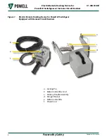
Page 12: ...ce for Powell LV Switchgear w Siemens Circuit Breakers Figure 1 Electric Remote Racking Device for Powell LV Switchgear Equipped with Siemens Circuit Breakers d c f b e a a Locking Pin b Motor Control Box Cord c Racking Handle Assembly d Hanger Bracket e Motor Control Box f Power Cord ...

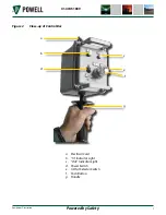
Page 13: ...afety 7 Equipment Description 01 4IB 51809 Figure 2 Close up of Control Box a Electrical Cord b In Indicator Light c Out Indicator Light d Power Switch e In Out Selector Switch f Push Button g Handle a b c e f d g ...

Page 14: ...age to the power connections may cause an electrical short The power cords should be inspected for any signs of damage prior to each use CAUTION C Storage Shipping and storage of electrical equipment requires measures to prevent the deterioration of the apparatus over a long unused period The mechanical and dielectric integrity must be protected Electrical equipment is designed for use in a variet...

Page 15: ... integrity 3 The auxiliary control devices ship loose material and protective relays must also be protected This includes items such as battery chargers UPS systems lighting installation hardware and air conditioning If prolonged storage is anticipated humidity controlling desiccant materials should be utilized Desiccant packets should be installed in all compartments and packing containers D Oper...

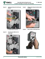
Page 16: ...vice for Powell LV Switchgear w Siemens Circuit Breakers Figure 3 Inserting Locking Pins into Hanger Bracket a a Breaker Position Indicator Figure 4 Connecting the Motor to the Control Box Figure 5 Sliding the Racking Handle Assembly into Place Figure 6 Activate Remote Racking Device ...

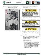
Page 17: ... Prior to inserting the circuit breaker into the circuit breaker compartment make sure that the control circuits are deenergized CAUTION Prior to inserting the circuit breaker into the circuit breaker compartment ensure that the circuit breaker is OPEN and the mechanism is discharged CAUTION Before using the electric racking device verify compliance with Siemens circuit breaker instruction bulleti...

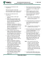
Page 18: ...fy the door is closed and latched and the breaker is tripped h Insert the cylindrical plug into the remote racking device motor Figure 4 Lock the plug by turning it clockwise i Ensure the motor control box power switch is in the OFF position Figure 2 d j Physically move the motor control box to a remote area and connect the power cord Figure 1 f to a 120VAC power source k When racking IN turn the ...

Page 19: ...lease This will hold the pin up and out of the way and make for easier installation f Lift the racking device by the handle Figure 3 a Position the device in place and insert the pin in the other half of the hinge mounted on the door Figure 3 a b g With the racking device secured to the door position the racking handle through the racking handle assembly on the racking device Figure 7 Make sure th...

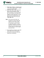
Page 20: ...king sound along with a vibration of the racking device At this point release the push button The breaker position indicator will read DISCONNECTED Note If the remote location that was selected is in a location where the breaker can not be seen and the torque limiter can not be heard it is suggested to perform a racking operation on dead bus and time the operation Document the time and rack the br...

Page 21: ...rk and inspections should be kept The degree of record detail depends on the operating conditions The record should include the dates and results starting from the date the device is first put into service Dates and results of inspections and routine maintenance activities should be recorded B Inspection and Cleaning Inspect the electric racking device for loose or damaged hardware or parts Tighte...

Page 22: ...2 Always specify the complete nameplate information including Device Type Serial Number Rated Voltage Rated Amps 3 Specify the quantity and description of the part and the instruction bulletin number If the part is in any of the recommended renewal parts tables specify the catalog number If the part is not in any of the tables a description should be accompanied by a marked illustration from this ...

Page 23: ...8 Houston TX 77217 Tel 713 944 6900 Fax 713 948 4569 www powellind com info powellind com 2006 Powell Industries Inc All rights reserved for use with Powell Low Voltage Switchgear Equipped with Siemens Circuit Breakers 01 4IB 51809 Electric Remote Racking Device 51897G31 November 2011 ...

Reviews: