
Power-Flo Pumps & Systems • 877-24PUMPS • www.powerflopumps.com
9
Power Cord:
8. Check power cord (19) for cracks
or damage and replace if required.
Reconnect motor leads.
9. Place power cord (19) with nylon
housing (15), ring (16), washer (17) and
gland nut (18) into housing (24) and
tighten gland nut to 17.5 ft/lbs.
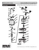
Impeller, V-ring and Volute:
10. Position v-ring (35) into seal plate (3)
until seated.
11. Clean the threads with thread locking
compound cleaner. Apply removable
Loctite® 242 or equivalent to shaft
threads. Screw impeller (37) onto the shaft
hand tight while using a screwdriver in
the slot at the end of the shaft to hold it
stationary. Rotate impeller to check for
binding.
12. Position gasket (2) on volute flange
and position impeller and motor housing
assembly on volute (1).
13. Place screws (36 into volute (1) and
torque to 11 ft/lbs. Check for free rotation
of impeller.
14. Refill with cooling oil.
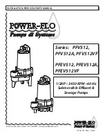
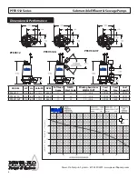
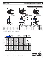
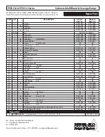
PFEV512 & PFV512 Series
Submersible Effluent & Sewage Pumps
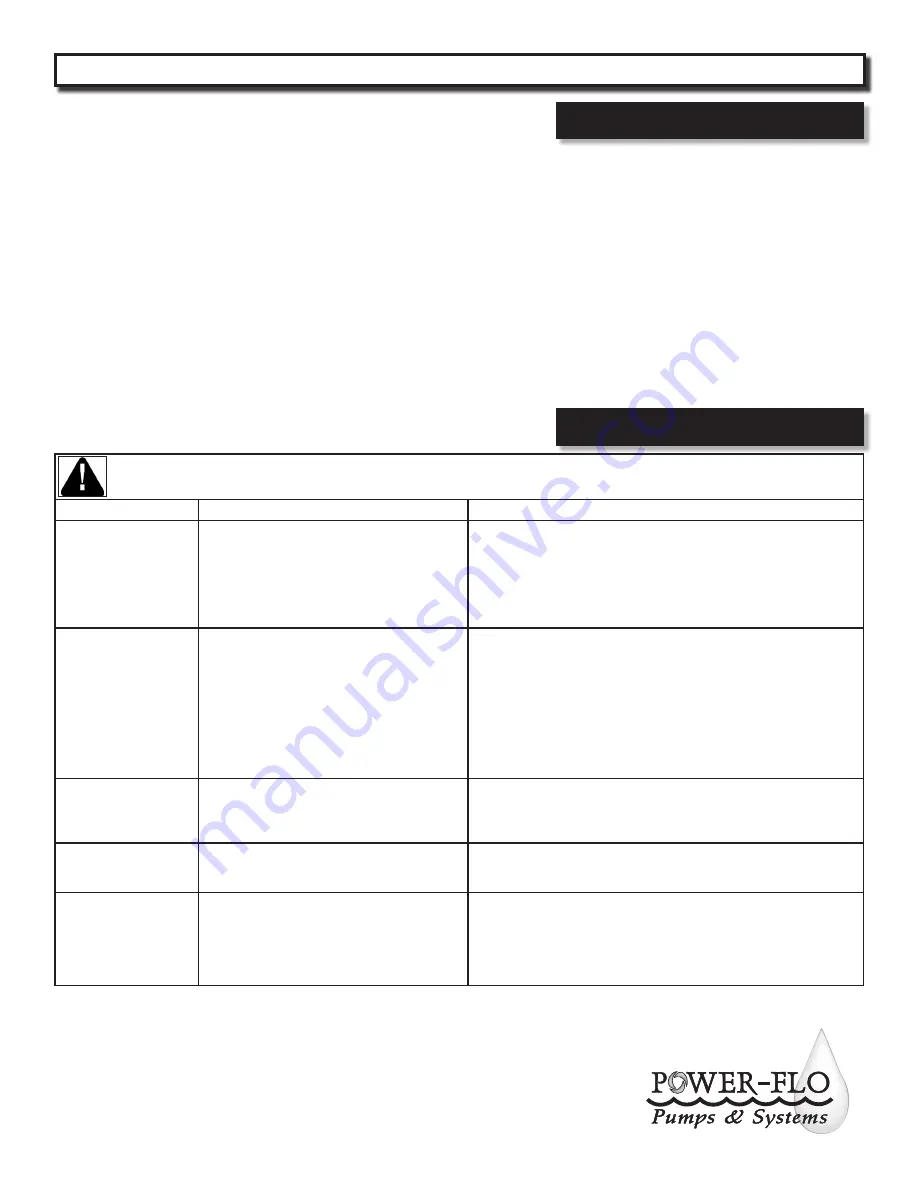
Service
Risk of electric shock. Always disconnect the pump from the power source before handling inspections or repairs.
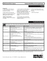
Symptom
Possible Cause(s)
Corrective Action
Pump will not run
1. Blown fuse or other interruption of
power; improper voltage.
2. Switch is unable to move to the “turn ON”
position due to interference with the side of basin
or other obstruction
3. Insufficient liquid level
4. Defective level control
1. Check that the unit is securely plugged in. Have an electrican check all
wiring for proper connections and adequate voltage and capacity.
2. Position the pump or switch so that it has adequate clearance for free
operation.
3. Make sure the liquid level is allowed to rise enough to activate level
control(s).
4. Remove and replace level controls
Pump will not turn off
1. Discharge is blocked or restricted
2. Check valve is stuck closed or installed
backwards
3. Gate or ball valve is closed
4. Total lift is beyond pump’s capability
5. Pump impeller is jammed or volute casing is
pluged
1. Check the discharge line for foreign material, including ice if discharge line
passes through or into cold areas
2. Remove check valve(s) and examine for freedom of operation and proper
installation
3. Open gate or ball valve
4. Try to route piping to a lower level.
If not possible, a larger pump may be required. Consult the factory
5. Disconnect unit electrically. Remove the pump from the basin. Detach the
pump base and clean the area around the impeller. Rotate impeller by hand.
Reassemble and reinstall
Pump will not turn off
1. Level control(s) unable to move to the “turn OFF”
position due to interference with the side of basin
or other obstacle
2. Defective level control
1. Posistion the pump or level control so that it has adequate clearance for
free operation
2. Remove and replace level control
Pump runs periodically
when fixtures are not in
use
1. Check valve is stuck open or is leaking
2. Fixtures are leaking
1. Remove check valve(s) and examine for freedom of operation and proper
installation
2. Repair fixtures as required to eliminate leakage
Pump operates noisily
1. Debris in the impeller cavity
2. Damaged impeller
3. Worn bearings
4. Piping attachments to building are too rigid
1. Remove the pump from the basin.
Detach the pump base and clean the area around the impeller. Reassemble
and reinstall
2. Consult the factory for information regarding replacement of impeller
3. Return pump to the factory or authorized repair station for repair
4. Replace a portion of the discharge line with rubber hose or connector
NOTE:
Power-Flo Pumps & Systems assumes no responsibility for damage or injury due to disassembly in the field. Disassembly of the pumps or supplied
accessories other than at Power-Flo Pumps & Systems or its authorized service centers, automatically voids warranty.
Trouble Shooting Chart


